
Meshed gear for vehicle

a technology of meshed gear and vehicle, which is applied in the direction of gearing, hoisting equipment, couplings, etc., can solve the problems of vehicle interior noise, booming noise of meshed gear, and vibration of the case surface of the transmission, so as to increase compliance, and reduce booming noise and rattling noise

Active Publication Date: 2014-01-16
TOYOTA JIDOSHA KK
View PDF20 Cites 2 Cited by
  • Summary
  • Abstract
  • Description
  • Claims
  • Application Information

AI Technical Summary

Benefits of technology

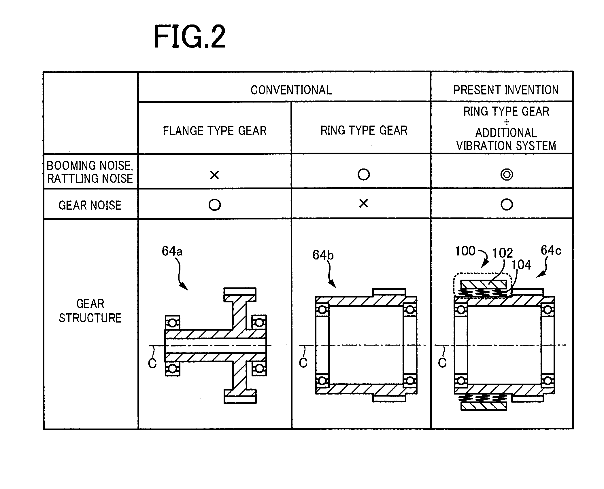
The patent describes a solution to reduce gear noise, booming noise, and rattling noise in a transmission. By making the gear into a ring shape and adding an additional vibration system, the moment of inertia is increased, which reduces the noise. The additional vibration system can be vibrated in the higher frequency range where gear noise occurs, to further reduce the noise. The elastic member used in the additional vibration system may be metal springs, which allows for effective vibration in the lower frequency range where booming noise and rattling noise occur, while also being inertial in the higher frequency range where gear noise occurs.

Problems solved by technology

Such a meshed gear is known to generate booming noise and rattling noise during power transmission.
The booming noise is vehicle interior noise occurring because vibrations are caused by torque variation of the engine and transmitted via a transmission (gearbox) through a drive shaft and a suspension to the inside of a vehicle.
The rattling noise is vehicle interior noise occurring because when vibrations are caused by torque variation of the engine and transmitted to the transmission, collision of gears with each other so-called rattling (tooth hitting) occurs in meshed gears in the transmission and the rattling causes a case surface of the transmission to vibrate and generate noise, which is transmitted to the inside of a vehicle.
It is also known that the meshed gear generates gear noise during power transmission.
Meshing of gears (a driving gear and a driven gear) always has a rotation angle error relative to ideal rotational motion.
The rotation angle error corresponds to an advance or a delay of the driven gear relative to the driving gear and is also referred to as a mesh transmission error.
This mesh transmission error is generated due to a manufacturing error of a gear, an assembly error, and elastic deformation of a gear, a support shaft, a case, etc., and the mesh transmission error cannot be set to zero.
The presence of the mesh transmission error generates a meshing point coercive force acting as a vibration source of the gear noise, resulting in the gear noise.

Method used


Image

  • Meshed gear for vehicle
  • Meshed gear for vehicle
  • Meshed gear for vehicle

Examples


example

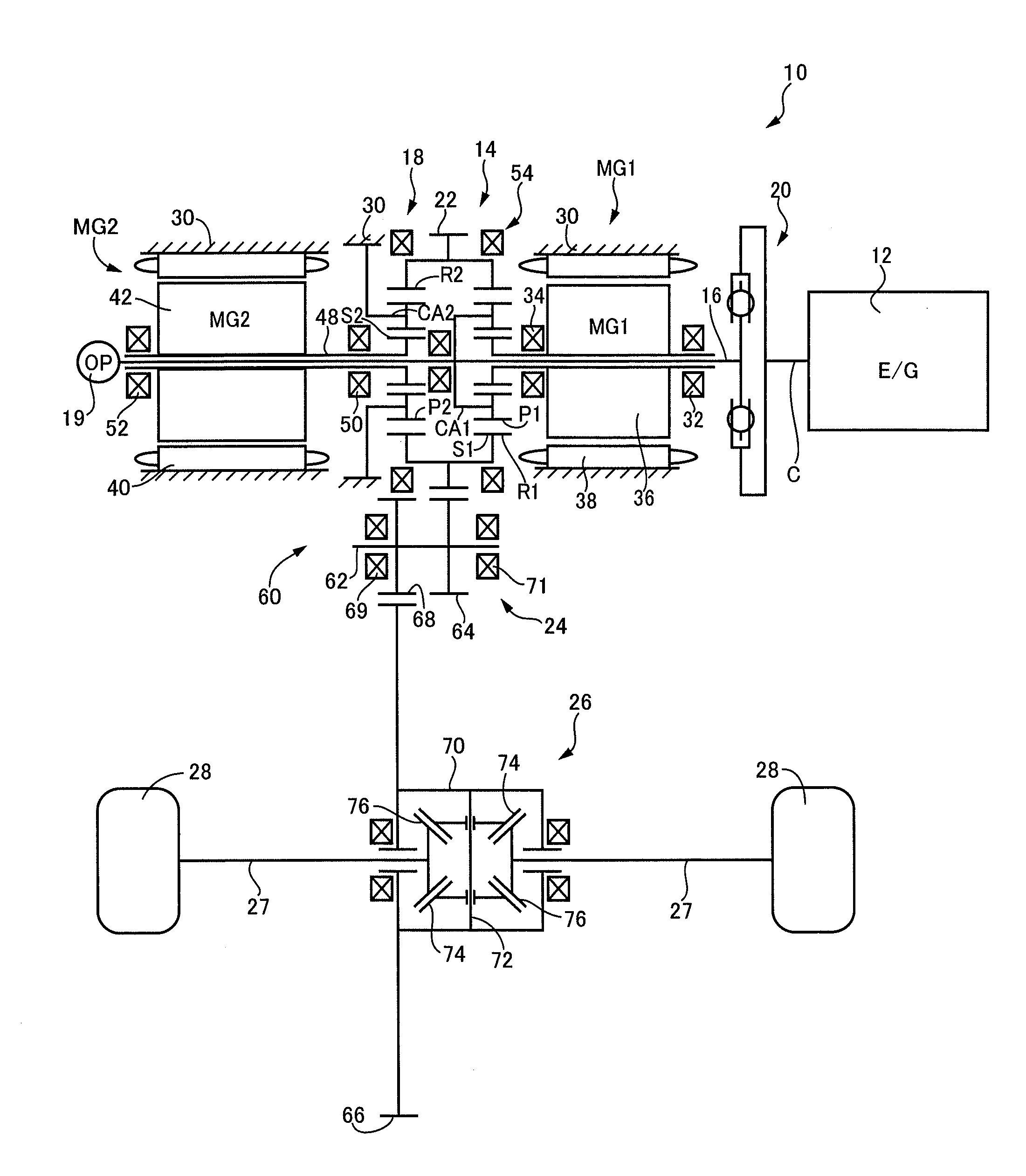
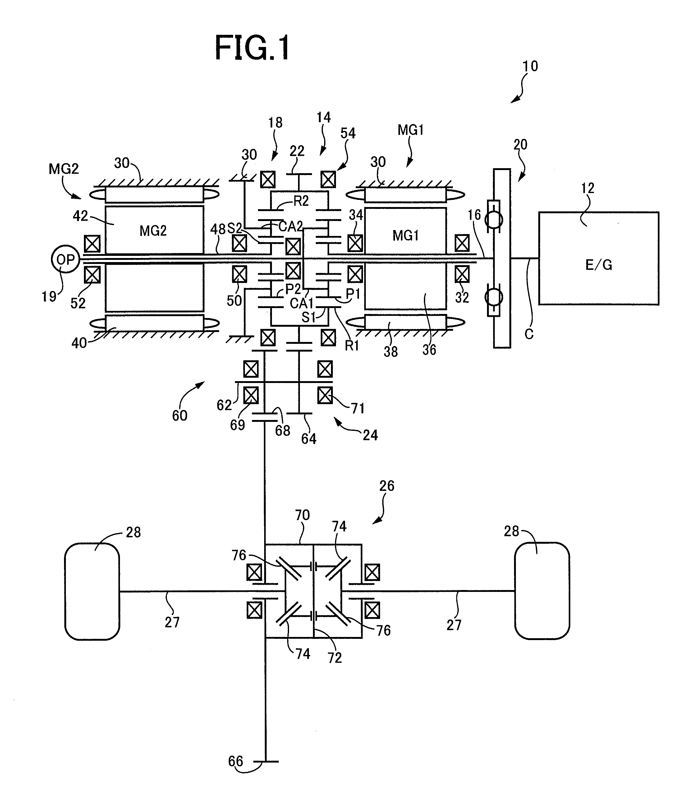
[0021]FIG. 1 is a schematic for explaining a general configuration of a hybrid vehicle power transmission device 10 (hereinafter referred to as a power transmission device 10) to which the present invention is applied. As depicted in FIG. 1, the power transmission device 10 includes an engine 12, a first electric motor MG1, a first planetary gear device 14 coupled to the engine 12 and the first electric motor MG1 in a power transmittable manner and acting as a power distribution mechanism appropriately distributing or combining the drive power of the engine 12 and the first electric motor MG1, a second electric motor MG2, and a second planetary gear device 18 acting as reduction gears reducing the rotation of the second electric motor MG2 on a coaxial center C. The drive power of the engine 12 is transmitted through a damper device 20, the first planetary gear device 14, an output gear 22, a reduction gear device 24, a differential gear device 26, and left and right axles 27 to driv...


PUM


Abstract

It is provided a meshed gear for a vehicle disposed in a power transmission path between an engine and drive wheels and made up of a pair of gears meshed with each other, at least one gear making up the meshed gear having a ring shape, and the one gear having an outer circumferential portion disposed with an additional vibration system.

Description

TECHNICAL FIELD[0001]The present invention relates to a structure of a meshed gear making up a power transmission path of a vehicle and particularly to a structure of a meshed gear achieving reduction of both booming and rattling noises and gear noise generated during power transmission through gears.BACKGROUND ART[0002]A power transmission path between an engine and drive wheels is disposed with a plurality of pairs of gears meshed with each other and drive power of the engine is transmitted via these meshed gears to the drive wheels. Such a meshed gear is known to generate booming noise and rattling noise during power transmission. The booming noise is vehicle interior noise occurring because vibrations are caused by torque variation of the engine and transmitted via a transmission (gearbox) through a drive shaft and a suspension to the inside of a vehicle. The rattling noise is vehicle interior noise occurring because when vibrations are caused by torque variation of the engine a...

Claims


Application Information

Patent Timeline
Patent Type & Authority Applications(United States)
IPC IPC(8): F16H1/04
CPCF16H1/04F16H55/14F16H57/0006Y10T74/19642
Inventor TAKEKAWA, HIROSHI
Owner TOYOTA JIDOSHA KK
Learn More