Control Arrangement For A Hydropneumatic Suspension System And Hydropneumatic Suspension System Comprising Such A Control Arrangement

a technology of hydropneumatic suspension and control arrangement, which is applied in the direction of resilient suspension, vehicle components, transportation and packaging, etc., can solve the problems of not always achieving the benefit of suspension properties, hardening the suspension, and strong oscillations about the transverse axis of the tractor

Active Publication Date: 2014-01-16
ARGO HYTOS GRP AG
View PDF12 Cites 5 Cited by
  • Summary
  • Abstract
  • Description
  • Claims
  • Application Information

AI Technical Summary

Benefits of technology

[0012]Adjusting the annular chamber pressure in the control arrangement according to the invention is carried out in dependence on the pressure prevailing in the piston chamber. If the pressure prevailing in the piston chamber is greater than a specific piston chamber pressure limit, which advantageously is adjustable, the pressure prevailing in the annular chamber is adjusted to a virtually constant value. If the piston chamber pressure falls below the piston chamber pressure limit, then, the farther the piston chamber pressure falls below the piston chamber pressure limit, the higher the annular chamber pressure is adjusted. The piston chamber pressure limit ideally corresponds to the pressure prevailing in the piston chamber at a suspension load that occurs when the tractor is not loaded. At low suspension loads, the annular chamber pressure that increases with decreasing piston chamber pressure causes an increase of the spring rate of the suspension system. In the range below the suspension load of the unloaded tractor and thus in the range of relatively low front axle loads as they occur for tractors with heavy rear-mounted attachments, the increasing spring rate counteracts potential pitching oscillations.
[0016]It is an advantage if the piston chamber connection is in flow connection with the control input of the hydraulically controllable pressure-limiting element via the control line, the flow rate of the hydraulic fluid flowing through the control line being limitable. Thus, the outflow of hydraulic fluid from the piston chamber connection to the control input of the hydraulically controllable pressure-limiting element can be limited.
[0017]In an advantageous embodiment, a flow resistance, for example a throttle or orifice, is provided in the control line. By using a flow resistance, the volume flow flowing off via the control line can be limited in a simple manner.
[0023]The invention also relates to a hydropneumatic suspension system in particular for vehicles. The hydropneumatic suspension system comprises a pump for generating pressure, a reservoir for hydraulic fluid and at least one suspension cylinder that has a piston chamber which carries the suspension load, is acted upon by pressure and is connected to a first hydraulic accumulator, and an annular chamber that sealingly surrounds a piston rod of the suspension cylinder, is acted upon by pressure and is connected to a second hydraulic accumulator. Moreover, the hydropneumatic suspension system comprises a control arrangement of the aforementioned kind, the piston chamber being connected to the piston chamber connection and the annular chamber being connected to the annular chamber connection. As already mentioned, such a hydropneumatic suspension system is characterized by low complexity, it being possible to keep the risk of pitching oscillations low. Moreover, the suspension system according to the invention has the advantage that it can be produced in a cost-effective manner, it being possible to use standard components with very low susceptibility to failure.

Problems solved by technology

This is not always of benefit to the suspension properties.
However, it is often useful, in particular in the case of low front axle loads, to increase the preload, thereby hardening the suspension.
This results in strong oscillations about the transverse axis of the tractor when driving over uneven ground.
These pitching oscillations can cause the suspension to bottom out.
However, this has the disadvantage that the suspension of an unloaded tractor is very hard and therefore offers only limited driving comfort.
This affects adversely not only the suspension properties of the suspension system but also the hydraulic accumulator connected to the annular chamber.
By means of an adjustable end stop, the movability of the positioning piston is limited.
However, disadvantageous are the high component costs and the complex control as well as the vulnerability to failure of such control arrangements for which no standard components can be used, so that producing such control arrangements is associated with significant costs.

Method used


Image

  • Control Arrangement For A Hydropneumatic Suspension System And Hydropneumatic Suspension System Comprising Such A Control Arrangement
  • Control Arrangement For A Hydropneumatic Suspension System And Hydropneumatic Suspension System Comprising Such A Control Arrangement
  • Control Arrangement For A Hydropneumatic Suspension System And Hydropneumatic Suspension System Comprising Such A Control Arrangement

Examples


first embodiment

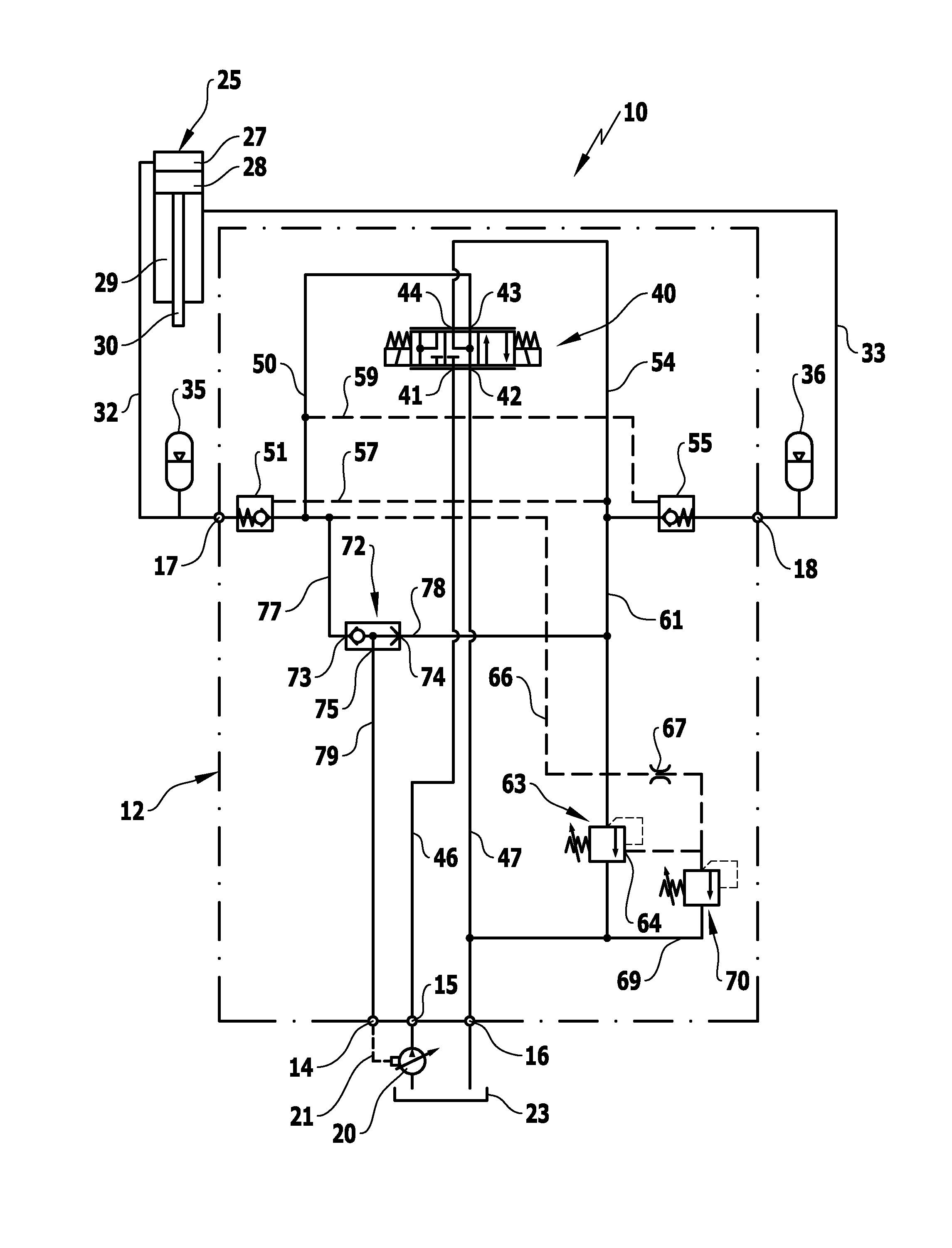
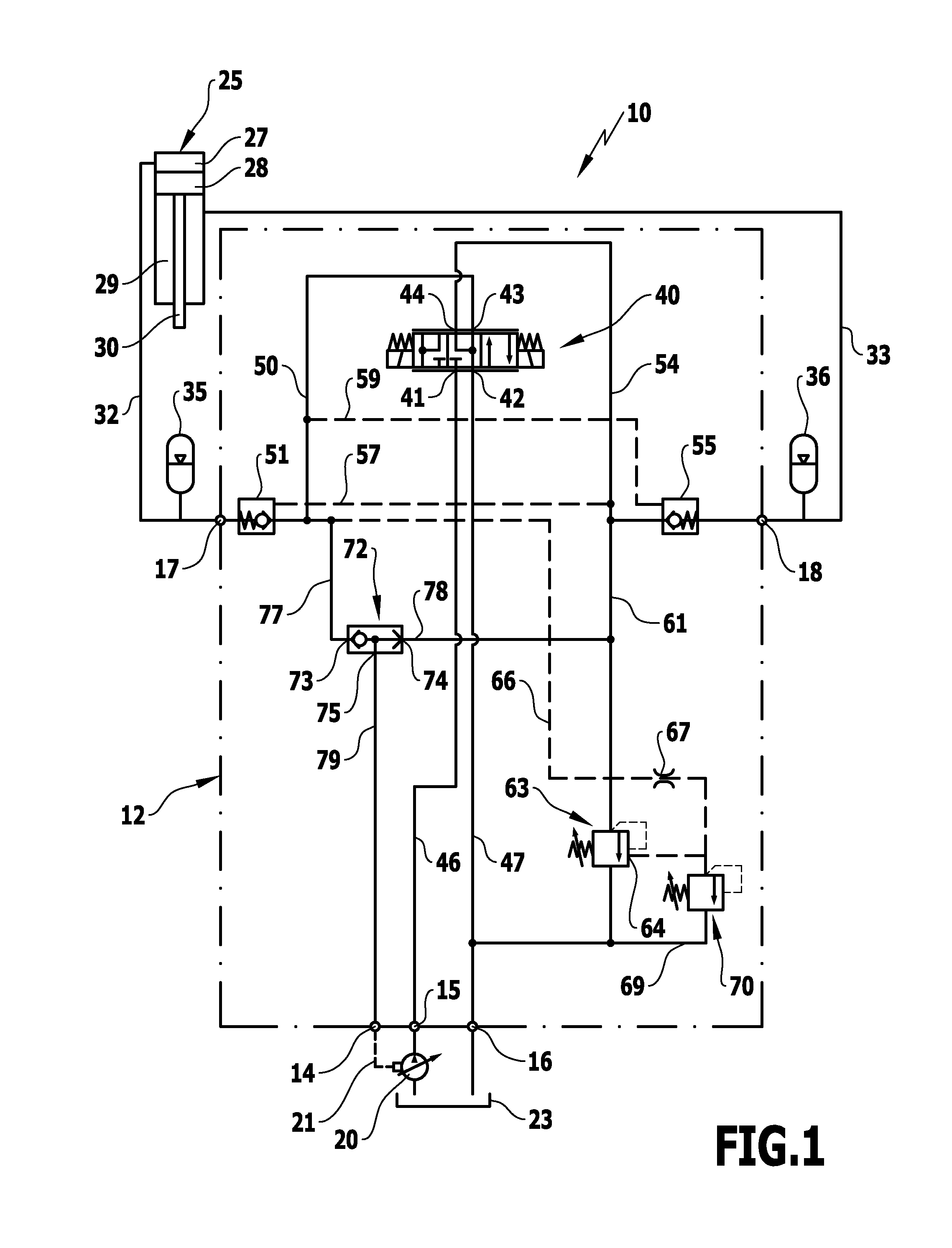
[0029]FIG. 1 illustrates schematically a hydropneumatic suspension system according to an advantageous embodiment of the invention that is designated as a whole by the reference number 10. The suspension system 10 is in particular suitable for use in vehicles with greatly varying load conditions, for example in tractors with holding means for attachments at the front and rear. In the suspension system illustrated in FIG. 1, a control arrangement according to the invention is used that is designated by the reference number 12 and that has a control connection 14, a pressure supply connection 15, a return connection 16 as well as a piston chamber connection 17 and an annular chamber connection 18. Connected to the pressure supply connection 15 is a load-sensing pump 20 that is controlled via a pump control line 21 connected to the control connection 14. A reservoir 23 is connected to the return connection 16.

[0030]In addition to the control arrangement 12, the hydropneumatic suspensio...

second embodiment

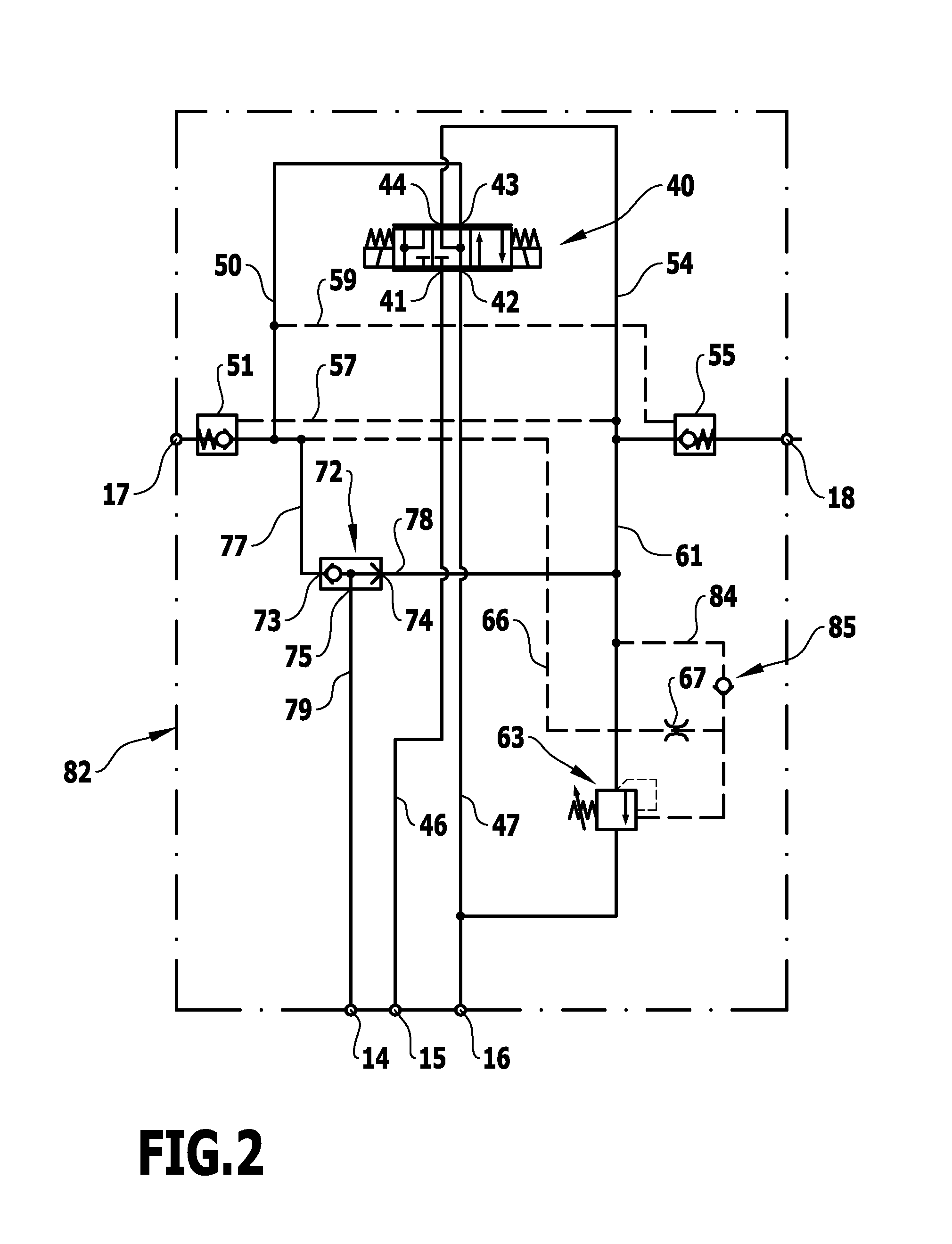
[0041]FIG. 2 illustrates a control arrangement according to the invention which, as a whole, is designated by the reference number 82. The control arrangement 82 can be used in the hydropneumatic suspension system 10 as an alternative to the above-described control arrangement 12. The control arrangement 82 is formed to be largely identical to the control arrangement 12. For identical components, the same reference numbers as in FIG. 1 are used in FIG. 2, and in order to avoid repetition with regard to these components, reference is made to the above explanations.

[0042]The control arrangement 82 differs from the control arrangement 12 in that in the region between the throttle element 67 and the control input 64 of the hydraulically controllable pressure-limiting valve 63, a connecting line 84, in which a check valve 85 is provided, branches off the control line 66 and ends in the first pressure-limiting line 61 on the high pressure side of the controllable pressure-limiting valve 6...


PUM


Abstract

A control arrangement for a hydropneumatic suspension system and a hydropneumatic suspension system are provided. The control arrangement has a pressure supply connection, a return connection, a piston chamber connection adapted to be connected to the piston chamber of a suspension cylinder of the hydropneumatic suspension system, an annular chamber connection adapted to be connected to the annular chamber of the suspension cylinder, and at least one controllable valve arrangement comprising a plurality of switch positions via which the pressure supply connection and the return connection are connectable to the piston chamber connection and the annular chamber connection. The annular chamber connection is in flow connection with the return connection via a pressure-limiting line having a hydraulically controllable pressure-limiting element. The pressure-limiting element has a control input adapted to be acted upon via a control line by a control pressure which is limitable to a predefinable pressure limit.

Description

[0001]This application claims the benefit of German application number 10 2012 106 185.8 filed Jul. 10, 2012, which is incorporated herein by reference in its entirety and for all purposes.BACKGROUND OF THE INVENTION[0002]The invention relates to a control arrangement for a hydropneumatic suspension system, in particular for vehicles, the control arrangement having a pressure supply connection for connecting to a pressure supply, a return connection, a piston chamber connection adapted to be connected to a piston chamber of a suspension cylinder of the hydropneumatic suspension system and adapted to be acted upon by a piston chamber pressure, an annular chamber connection adapted to be connected to the annular chamber of the suspension cylinder and adapted to be acted upon by an annular chamber pressure, and at least one controllable valve arrangement which comprises a plurality of switch positions through which the pressure supply connection and the return connection are connectabl...

Claims


Application Information

Patent Timeline
Patent Type & Authority Applications(United States)
IPC IPC(8): B60G17/08
CPCB60G17/08B60G17/04B60G17/0408B60G17/056B60G2500/02
Inventor BAUER, WOLFGANG
Owner ARGO HYTOS GRP AG
Why Eureka
Try Eureka