Clutch disk and friction clutch system

A technology of friction clutch and clutch disc, which is applied in the field of friction clutch device and driving system, to achieve the effect of improving torque transmission, improving driving comfort and improving vibration reduction

Active Publication Date: 2017-02-22
SCHAEFFLER TECH AG & CO KG
View PDF9 Cites 1 Cited by
  • Summary
  • Abstract
  • Description
  • Claims
  • Application Information

AI Technical Summary

Problems solved by technology

Especially to further

Method used


Image

  • Clutch disk and friction clutch system
  • Clutch disk and friction clutch system
  • Clutch disk and friction clutch system

Examples


Embodiment Construction

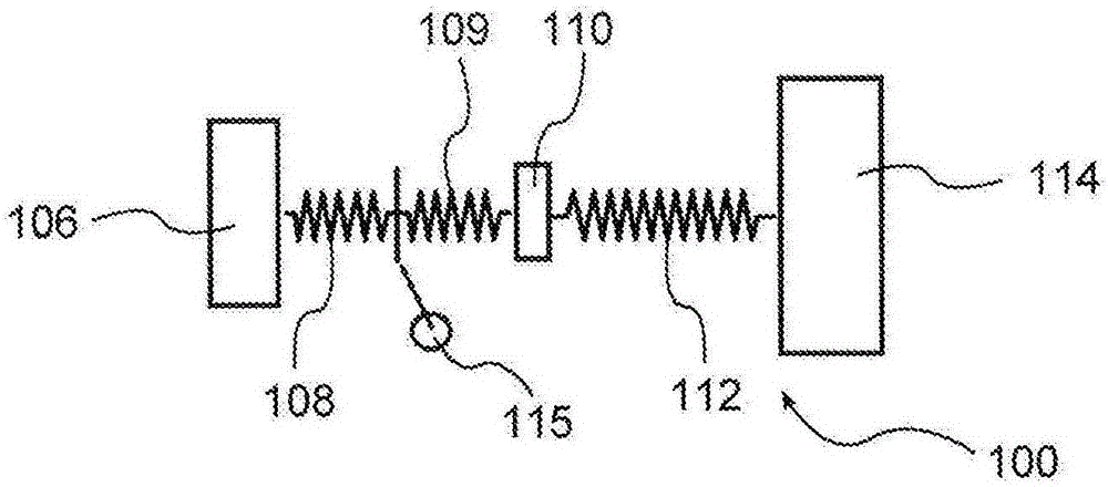
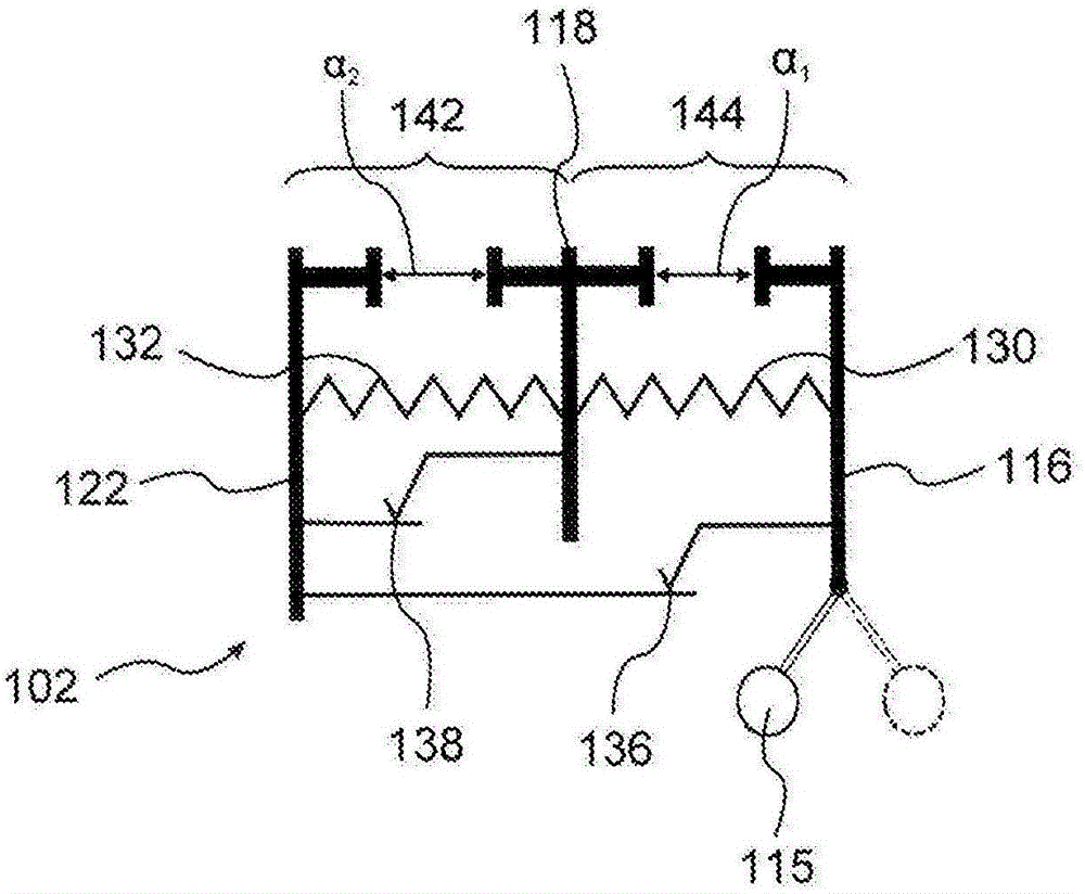
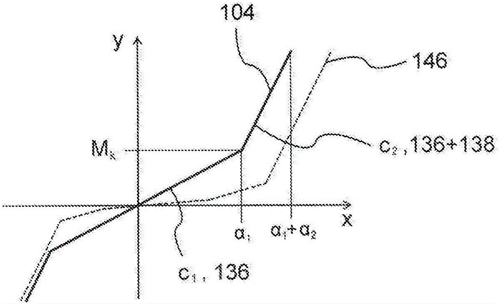
[0040] figure 1 A driveline 100 of a vehicle is shown. figure 2 A clutch disc 102 of the drive train 100 is shown. image 3 A characteristic line 104 of the clutch disc 102 is shown.

[0041] The drive train 100 has an internal combustion engine and a flywheel. The internal combustion engine and the flywheel have a joint moment of inertia 106 . Driveline 100 includes a friction clutch having clutch plates 102 . The clutch disc 102 has a torsional stiffness 108 . Drive train 100 has a transmission. The transmission has a transmission input shaft. The transmission input shaft has torsional stiffness 109 . The transmission has a moment of inertia 110 . Drive train 100 has vehicle wheels that can be driven. The driveline section between the transmission and the vehicle wheels has torsional stiffness 112 . The vehicle has a moment of inertia 114 . The centrifugal pendulum device 115 is arranged on the clutch disk 102 . The centrifugal pendulum device 115 simply increas...


PUM


Abstract

The invention relates to a clutch disk (102) for a friction clutch system, particularly for a powertrain of an internal combustion engine-driven vehicle, said clutch disk (102) comprising a disk rotation axis; an input part (122), at least one intermediate part (118) and an output part (116), wherein the input part (122) and the at least one intermediate part (118) on one hand, and the at least one intermediate part (118) and the output part (116) on the other hand, can be rotated relative to each other to a limited extent; and a centrifugal force pendulum device (115) which is mounted on the output part (116), the clutch disk (102) having a characteristic line with a lower load range and an upper load range, and an increased spring stiffness being effective in the lower load range. The invention also relates to a friction clutch system, in particular for a powertrain of an internal combustion engine-driven motor vehicle, said friction clutch system comprising a clutch rotation axis, a housing, at least one pressure plate, at least one contact plate which can be axially moved relative to the pressure plate to a limited extent between an engaged actuation position and a disengaged actuation position for the purpose of actuation, and to at least one such clutch disk (102) which can be clamped between the at least one pressure plate and the at least one contact plate for frictional power transmission.

Description

technical field [0001] The invention relates to a clutch disc for a friction clutch device, in particular for a drive train of a vehicle driven by an internal combustion engine, said clutch disc having: a disc rotation axis; an input part; at least one intermediate part; and an output part, wherein a On the one hand the input part and the at least one intermediate part are capable of limited twisting relative to each other, and on the other hand the at least one intermediate part and the output part are capable of limited rotation relative to each other; and arranged on the output part Centrifugal pendulum device. Furthermore, the invention relates to a friction clutch device, in particular for a drive train of a vehicle driven by an internal combustion engine, which has a clutch axis of rotation, a housing, at least one pressure plate and at least one pressure plate , the compression plate is axially displaceable in a limited manner relative to the pressure plate for manipul...

Claims


Application Information

Patent Timeline
IPC IPC(8): F16F15/123F16F15/14F16D13/64
CPCF16D13/64F16F15/12366F16F15/1238F16F15/145F16F2228/06F16F2228/14
Inventor U·韦勒S·莱曼H·朗根埃克特W·阿尔贝特A·鲁施
Owner SCHAEFFLER TECH AG & CO KG
Why Eureka
Try Eureka