Micromechanical device including a stop spring structure

a technology of stop spring and micromechanical device, which is applied in the direction of microstructural device, acceleration measurement using interia force, instruments, etc., can solve the problems of increasing the tendency of hard fixed stop, affecting the adhesion rate of the component, and possibly damaging the anti-adhesion layer more strongly, so as to achieve the effect of reducing the shear load between the stop and the substrate surface of the micromechanical device, high spring stiffness and low spring stiffness

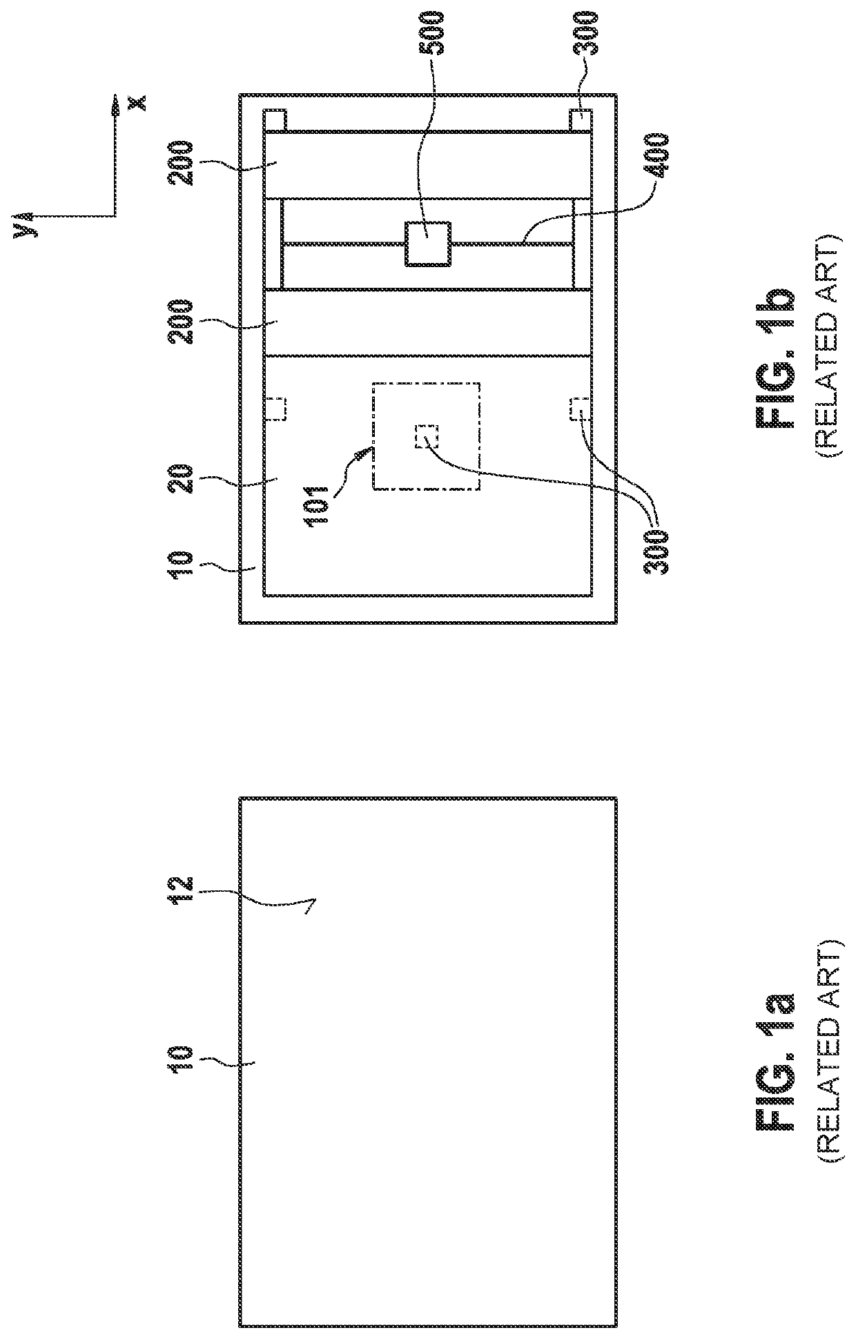
Active Publication Date: 2021-10-21
ROBERT BOSCH GMBH
View PDF12 Cites 1 Cited by
  • Summary
  • Abstract
  • Description
  • Claims
  • Application Information

AI Technical Summary

Benefits of technology

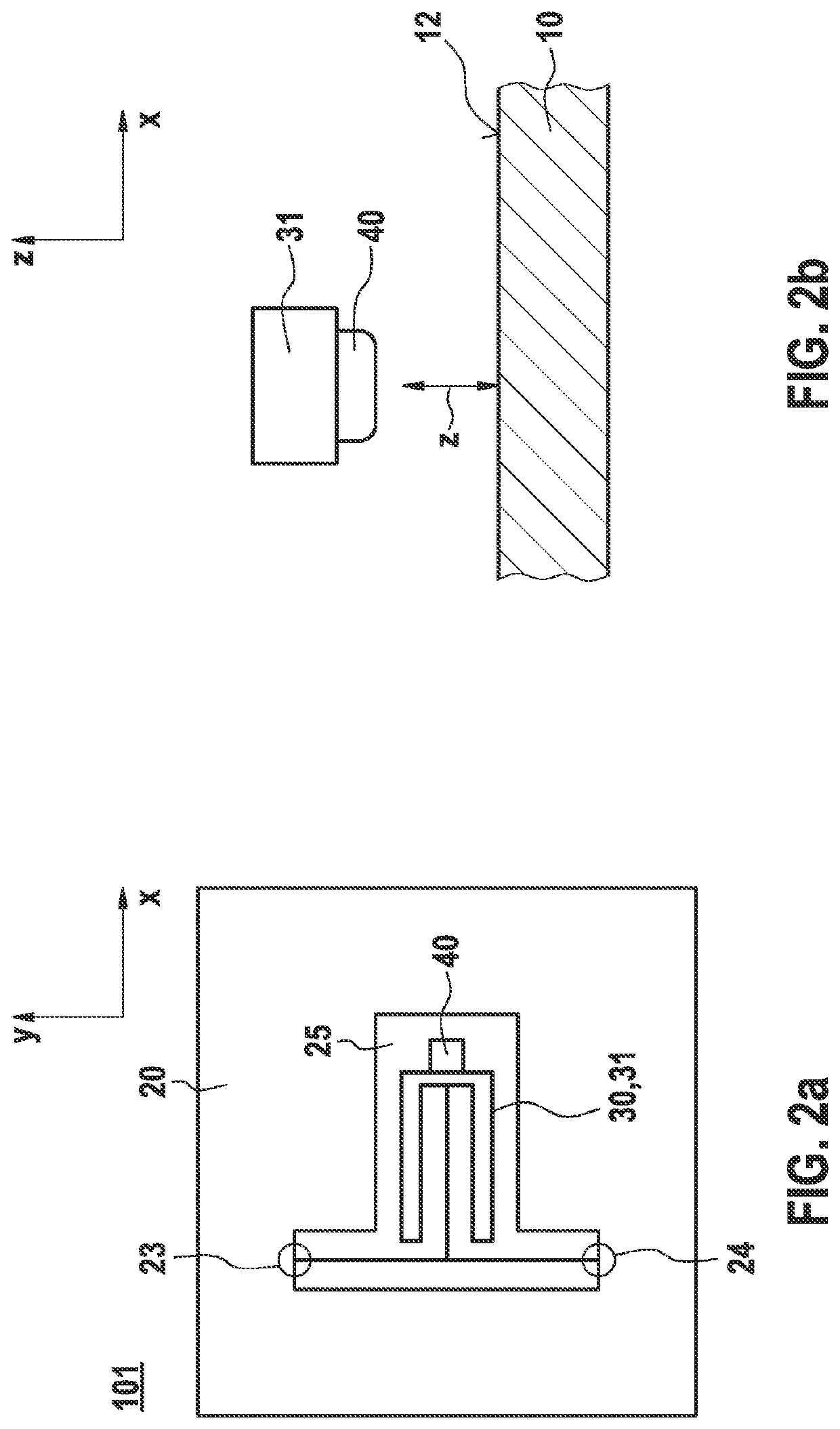
[0012]According to an example embodiment of the present invention the present invention, the stop spring structure of the z stop of a movable mass is designed in such a way that it has a defined, comparatively high spring stiffness in the z direction and in addition a very low spring stiffness in at least one direction x or y perpendicular thereto. Shear loads between the stop and the substrate surface of the micromechanical device are thus advantageously reduced.
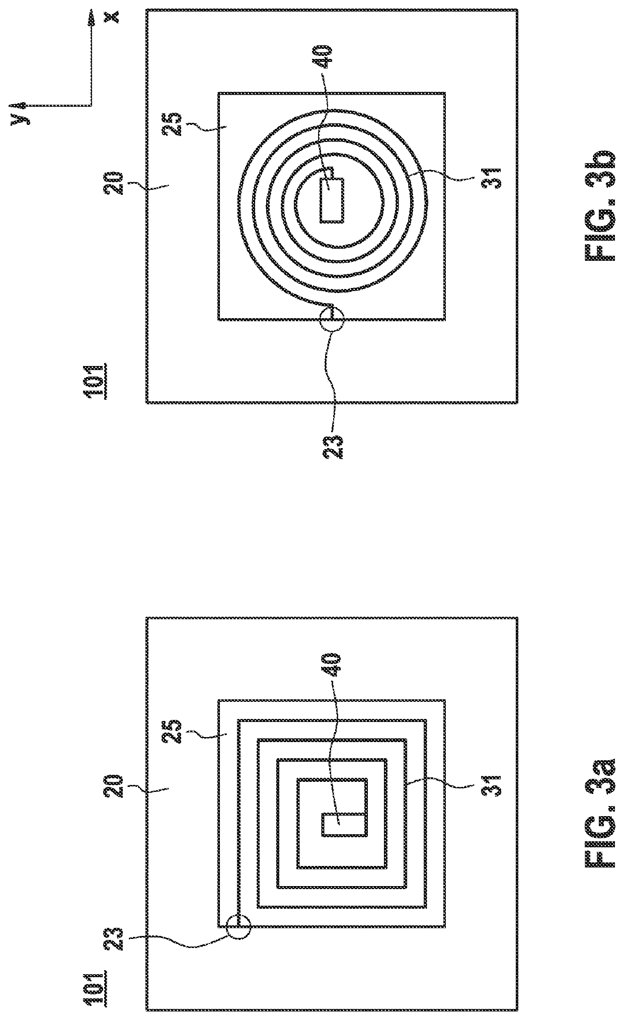
[0013]One advantageous embodiment of the present invention provides that the stop spring structure includes a first stop spring which is connected to the movable mass in at least one first connecting area. It is particularly advantageous that the first stop spring is connected to the movable mass in a second connecting area and is a torsion spring or a meander spring or a combination thereof. Such springs may advantageously be made very soft in parallel to the main extension plane. The rocker function of a torsion spring may thus also advantageously be linked to the deflectability in the x and y directions.

Problems solved by technology

One possible error pattern is the adherence, in which the movable sensor mass remains stuck on a mechanical fixed stop when the adhesion forces in the stop are greater than the restoring forces of the spring-mass system.
The novel load profiles may also have the result that the tendency to adhere increases over the lifetime of the component.
However, a hard fixed stop tends toward the above-described error mechanisms (adherence, particle formation) in the event of frequent overload.
The anti-adhesive layer is possibly damaged more strongly by the lateral sliding over the contact surface than in the case of a solely vertical contact.

Method used


Image

  • Micromechanical device including a stop spring structure
  • Micromechanical device including a stop spring structure
  • Micromechanical device including a stop spring structure

Examples


Embodiment Construction

[0022]The force acting on a spring is, in a first approximation, proportional to the deflection of the spring.

[0023]F=K*L, where F is the force, K the spring constant, and L the deflection.

[0024]The stop spring structure of the device according to the present invention enables deflections in all (Cartesian) spatial directions x, y, z. The stop spring structure includes different spring constants and thus different restoring forces as a function of the direction of the deflection.

F(x,y,z)=K(x,y,z)*L(x,y,z)

[0025]In order that, if possible, no lateral movement results over the surface of the stop in the x or y direction, the spring constant, also referred to as the spring rigidity or spring stiffness, perpendicular to stop direction z is to be less than a certain percentage of the spring stiffness in the stop direction. This results from the coefficient of friction and from the maximum expectable force vector if one presumes that the external force vector during an impact does not sign...


PUM


Abstract

A micromechanical device including a substrate, a movable mass, and a stop spring structure, which includes a stop. The substrate includes a substrate surface in parallel to a main extension plane and the movable mass is situated movably above the substrate surface in relation to the substrate. The stop spring structure is connected to the movable mass. The stop is designed to strike against the substrate surface in the event of a deflection of the movable mass in a z direction, perpendicular to the main extension plane. The stop spring structure, at the location of the stop, includes a first spring constant, a second spring constant, in parallel to the main extension plane, and a third spring constant, in parallel to the main extension plane and perpendicular to the x direction. The first spring constant is greater than the second spring constant and / or is greater than the third spring constant.

Description

CROSS REFERENCE[0001]The present application claims the benefit under 35 U.S.C. § 119 of German Patent Application No. DE 102020204767.7 filed on Apr. 15, 2020, which is expressly incorporated herein by reference in its entirety.BACKGROUND INFORMATION[0002]The present invention is directed to a micromechanical device including a substrate, a movable mass, and a stop spring structure, which includes a stop, the substrate including a substrate surface in parallel to a main extension plane x, y and the movable mass being situated movably in relation to the substrate above the substrate surface, the stop spring structure being connected to the movable mass and the stop being designed to strike against the substrate surface in the event of a deflection of the movable mass in a z direction, perpendicular to main extension plane x, y. Such devices are available in the related art, for example, as z acceleration sensors in a rocker construction.[0003]Micromechanical inertial sensors for mea...

Claims


Application Information

Patent Timeline
Patent Type & Authority Applications(United States)
IPC IPC(8): B81B3/00
CPCB81B3/0027G01P15/08B81B5/00B81B3/0051B81B2201/025G01C19/5755G01P2015/0831G01P2015/0871G01P2015/0874G01P15/125G01P2015/086
Inventor NAGEL, CRISTIANCLASSEN, JOHANNESSCHEBEN, ROLFEID, RUDY
Owner ROBERT BOSCH GMBH
Why Eureka
Try Eureka