Machine tools including punching units and laser processing units

A technology of laser processing and stamping devices, which is used in metal processing machinery parts, metal processing, auxiliary devices, etc.

Active Publication Date: 2020-02-18
TRUMPF WERKZEUGMASCHINEN GMBH & CO KG
View PDF8 Cites 0 Cited by
  • Summary
  • Abstract
  • Description
  • Claims
  • Application Information

AI Technical Summary

Problems solved by technology

[0008] Since both the punching device and the laser processing device are fastened to the frame, there is a risk that vibrations and shocks occurring during the punching operation of the machine tool will be transferred to the laser processing device arranged in the parking position

Method used


Image

  • Machine tools including punching units and laser processing units
  • Machine tools including punching units and laser processing units
  • Machine tools including punching units and laser processing units

Examples


Embodiment Construction

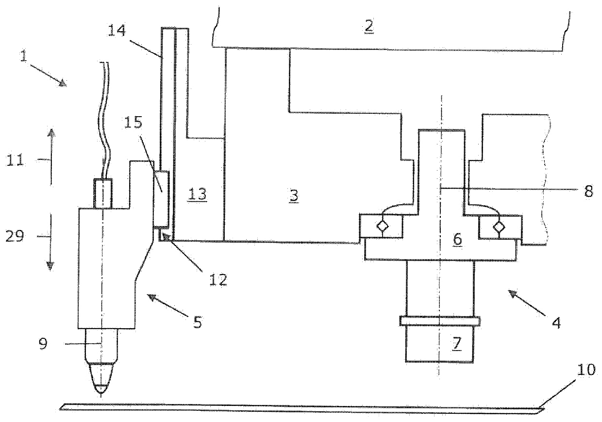
[0028] according to figure 1 , the machine tool 1 designed as a stamping-laser combination machine comprises a frame 2 . Support structure 3 can be perpendicular to on frame 2 figure 1 The view plane moves. The support structure 3 is equipped with a stamping device 4 and a laser processing device in the form of a laser cutting head 5 . Both the stamping device 4 and the laser cutting head 5 are of conventional design.

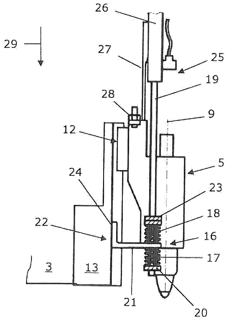
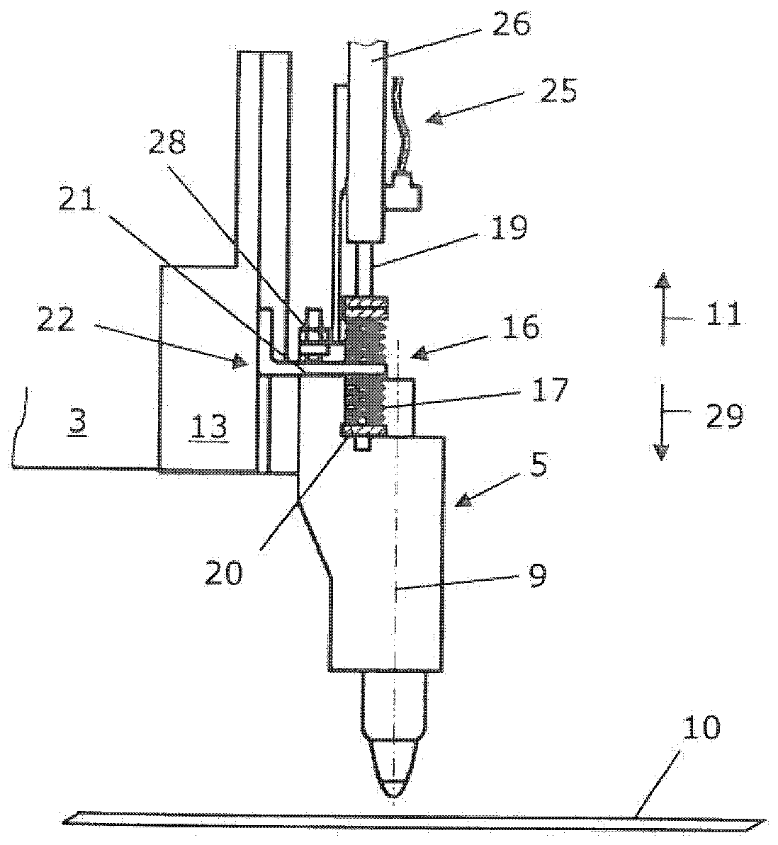
[0029] The punching device 4 generally comprises a punch 6 with a tool holder 7 into which punches can be introduced. By means of a drive (not shown in detail), the punch 6 can be moved along the punch stroke axis 8 together with the tool holder 7 and the punch introduced into the tool holder 7 through the working stroke and the return stroke after the working stroke, and can It is adjusted rotationally about the stamping stroke axis 8 . The laser cutting head 5 can be positioned along the laser positioning axis 9 in a manner described in more detail below...


PUM


Abstract

A machine tool for machining workpieces comprising a support structure, a punching device mounted on the support structure, and a laser machining device mounted on the support structure. The machine tool includes a suspension device provided between the punching device and the laser machining device to reduce the laser machining device from being stimulated to move unintentionally due to the operation of the punching device. The suspension device has a spring rate which can be adjusted by a laser positioning device. The laser positioning device can move the laser machining device relative to the workpiece into a functional position and also into a position remote from the functional position. The spring rate of the suspension device is adjusted such that the functional position of the laser machining device is assigned a higher spring rate than that assigned to the position of the laser machining device remote from the functional position.

Description

technical field [0001] The invention relates to machine tools for machining workpieces, especially sheet metal, which [0002] including support structures, [0003] comprising a punching device mounted on a support structure and by means of which a workpiece can be punched, [0004] comprising a laser processing device mounted on a support structure and by means of which a workpiece can be laser processed, and the laser processing device being connected to a punching device by means of a support structure such that operation of the punching device can excite said processing device move, [0005] Including a laser positioning device, for positioning the laser processing device relative to the workpiece, by means of the laser positioning device, the laser processing device can be moved by an activation movement into a functional position and a position away from the functional position, and the workpiece can be positioned in the functional position. the laser processing devi...

Claims


Application Information

Patent Timeline
Patent Type & Authority Patents(China)
IPC IPC(8): B23P23/04
CPCB23P23/04B23K26/0093B23K26/0869B23K37/0241B23K37/0461B26F1/38B23K2101/18B23Q11/0032
Inventor D·特纶克莱因
Owner TRUMPF WERKZEUGMASCHINEN GMBH & CO KG
Why Eureka
Try Eureka