Damping Valve For A Vibration Damper

a technology of vibration damper and damping valve, which is applied in the direction of shock absorbers, vibration dampers, springs/dampers, etc., can solve the problems of high area pressure on the valve disk to be deformed, and achieve the effect of limiting the lift of the valve disk, constant material thickness, and simple construction

Active Publication Date: 2019-10-03
ZF FRIEDRICHSHAFEN AG
View PDF0 Cites 0 Cited by
  • Summary
  • Abstract
  • Description
  • Claims
  • Application Information

AI Technical Summary

Benefits of technology

[0012]An especially simple construction is characterized in that the coating is carried out off-center with respect to a main axis of the valve disk.
[0013]Valve disks are often fixedly clamped in at the inner diameter or outer diameter such that only the free diameter lifts from the valve seat surface. The coating is carried out outside of a clamping surface of the valve disk so that no additional spring effect is introduced into the clamping chain between valve disk and damping valve body via the coating.
[0014]In addition to the function of the defined lift movement, it can also be provided that the coating is formed as a stop limit in lift direction of the valve disk. Impact noises, e.g., at a supporting disk of the damping valve, are prevented in this way. The supporting disk serves to limit the lift of the valve disk.
[0015]Alternatively or additionally, the coating can be carried out in impact direction on the valve seat surface in order to prevent impact noises during the closing movement.
[0016]The coating makes it possible to use a valve disk having constant material thickness and to dispense with axial projections in that the coating has axially protruding orientation elements which align the valve disk with respect to individual valve seat surface.

Problems solved by technology

However, an associated problem exists in that the valve disk to be deformed is exposed to a high area pressure in the region of the contacting edges of the neighboring disk.

Method used


Image

  • Damping Valve For A Vibration Damper
  • Damping Valve For A Vibration Damper
  • Damping Valve For A Vibration Damper

Examples


Embodiment Construction

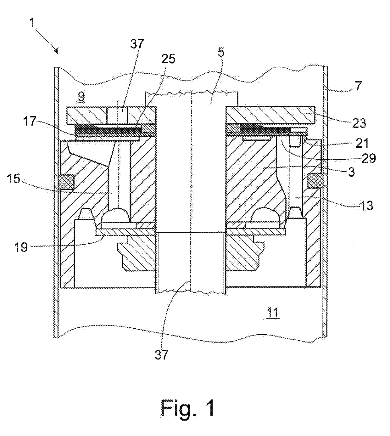
[0025]FIG. 1 shows a damping valve 1 for a vibration damper of any constructional type. Damping valve 1 comprises a damping valve body 3 fastened to a piston rod 5. The invention is not limited to an embodiment form of this type and can be used, e.g., in a bottom valve or also within the framework of an adjustable damping valve.

[0026]Damping valve body 3 divides a cylinder 7 of the vibration damper into a working chamber 9 on the piston rod side and a working chamber 11 remote of the piston rod. Both working chambers 9; 11 are filled with damping medium. Through-channels 13; 15, each for a flow direction, are formed on different pitch circles in damping valve body 3. The configuration of the through-channels is to be considered as exemplary only. An outlet side of through-channels 13; 15 is at least partially covered by at least one valve disk 17; 19.

[0027]When there is an incident flow against valve disk 17 proceeding from the working chamber 11 remote of the piston rod 5, valve di...


PUM


Abstract

A damping valve for a vibration damper includes a damping valve body with a through-channel whose outlet opening is at least partially closed by at least one elastically deformable valve disk. A further valve element is associated with the valve disk. This further valve element predetermines a defined lift behavior for the valve disk proceeding from a valve seat surface. The further valve element is formed by an elastic coating of the valve disk that exerts a varying supporting force with respect to the valve disk via the configuration of the top surface of the valve disk.

Description

CROSS REFERENCE TO RELATED APPLICATIONS[0001]This is a U.S. national stage of application No. PCT / EP2017 / 070448, filed on Aug. 11, 2017. Priority is claimed on German Application No. DE102016218373.7, filed Sep. 23, 2016, the content of which is incorporated herein by reference.BACKGROUND OF THE INVENTION1. Field of the Invention[0002]The invention is directed to a damping valve for a vibration damper.2. Description of Prior Art[0003]Up to the present time, there has been a pronounced effort toward a defined lifting behavior of a valve disk from a damping valve body, which can prevent noise from abruptly lifting valve disks.[0004]A proven remedy is a combination of two valve disks, one valve disk having a cutout at the edge into which the adjacent valve disk can penetrate. U.S. Pat. No. 5,529,154 discloses this constructional form in different variants. However, an associated problem exists in that the valve disk to be deformed is exposed to a high area pressure in the region of the...

Claims


Application Information

Patent Timeline
Patent Type & Authority Applications(United States)
IPC IPC(8): F16F9/348
CPCF16F9/3484
Inventor KNEZEVIC, ALEKSANDARRÖSSELER, JÖRG
Owner ZF FRIEDRICHSHAFEN AG
Why Eureka
Try Eureka