Apparatus and method for the dredging of sediments from the seabed

a technology of dredging apparatus and sediment, applied in the field of dredging systems, can solve the problems of insufficient solution, low efficiency of dredging apparatus, and decrease in efficiency, and achieve the effect of adequate slowing down and reducing the average speed

Active Publication Date: 2014-01-16
DECOMAR
View PDF14 Cites 21 Cited by
  • Summary
  • Abstract
  • Description
  • Claims
  • Application Information

AI Technical Summary

Benefits of technology

[0188]In a preferred embodiment, the dredging method further comprises the step of reducing the average speed of the water / sediment slurry sucked inside the suction head downstream of the suction opening.
[0189]Preferably, this speed reduction step is carried out by means of the aforementioned increase of the cross-section area of the lower portion of the suction head proximal to the suction opening and it allows an adequate slowing down of the sucked solid material (sediments but also broken stone or various kinds of debris).

Problems solved by technology

The Applicant has found that the aforementioned known dredging apparatuses which make use of pumps have a series of drawbacks for which an adequate solution has not yet been found.
A first drawback is essentially related to the fact that the agitating / disgregating devices that are used allow to operate with a content of solid material in the water / sediment mixture which does not normally exceed 20-25 volume % (normally equivalent to 40-45% by weight) and in any case with decreasing efficiency as the dredging depth increases.
The need to suspend the sediments implies in turn a low efficiency of the dredging apparatus, i.e. the need to move very high flow rates of water to achieve the removal of the sediments, with undesired additional negative consequences in terms of size of the pump, of its driving motor, of the discharge ducts, and therefore with inevitable negative consequences in terms of time and cost of the dredging operations.
A second serious drawback is essentially related to the fact that the agitating / disgregating devices which are used generate a water turbidity which makes dredging apparatuses of the so-called sucking-discharging type unable to be used in dredging sites of the SCI type (Site of Community Importance), SNI type (Site of National Importance) or in any case in areas where for environmental reasons it is not permitted to create any kind of water turbidity and / or any dispersion of polluting sediments in the water.

Method used


Image

  • Apparatus and method for the dredging of sediments from the seabed
  • Apparatus and method for the dredging of sediments from the seabed
  • Apparatus and method for the dredging of sediments from the seabed

Examples


Embodiment Construction

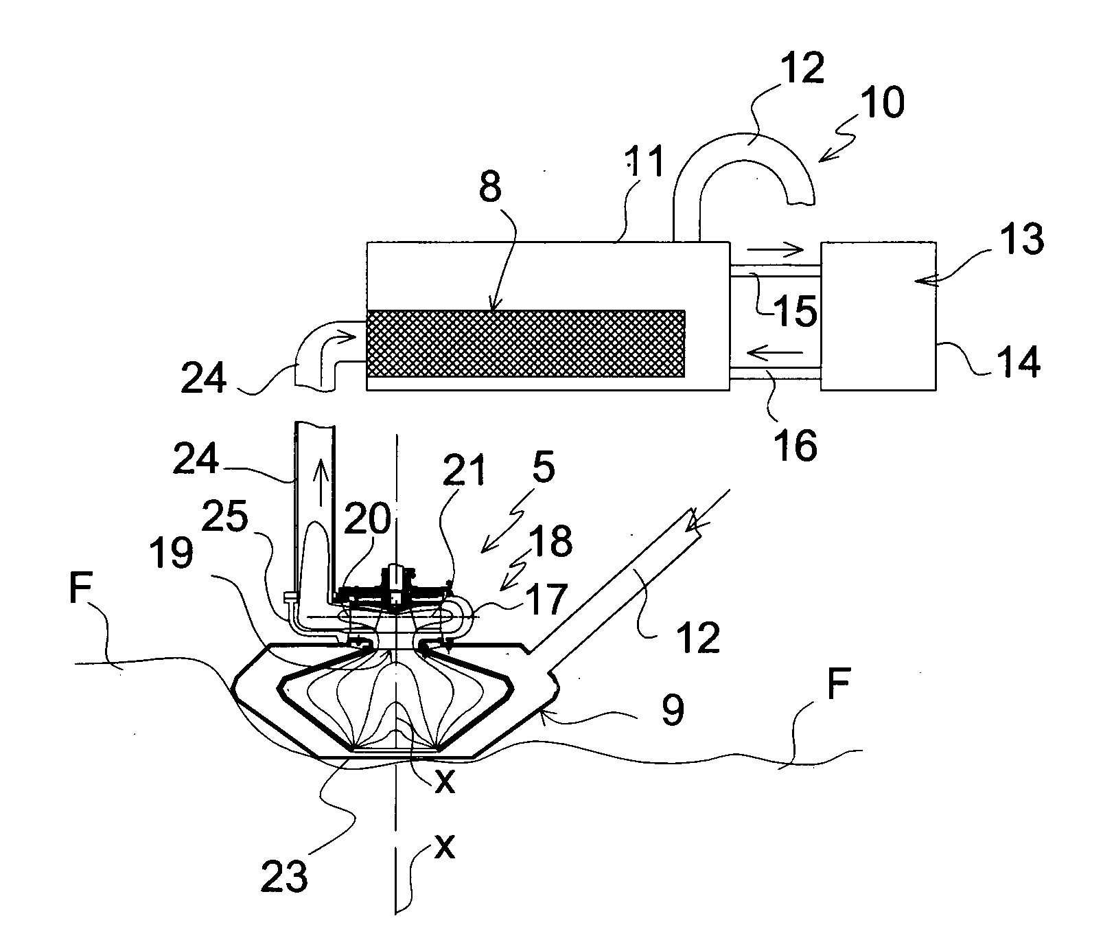
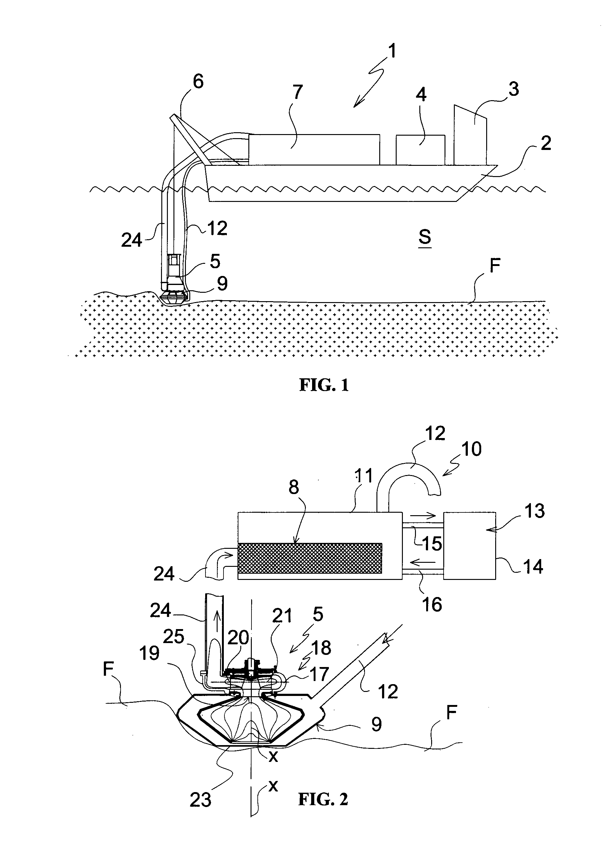
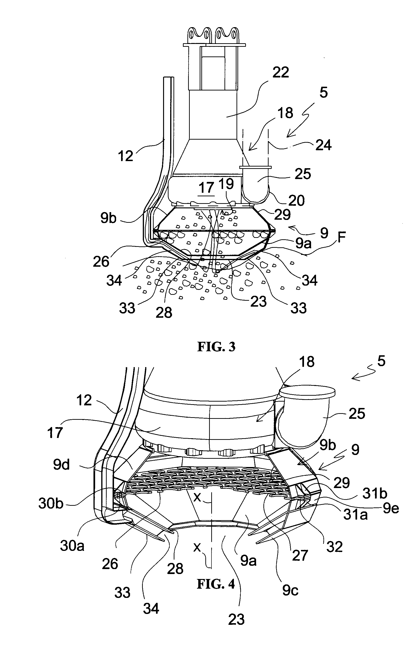
[0237]With reference to FIGS. 1-5, a dredging apparatus according to a first preferred embodiment of the invention, for example a dredging apparatus of the so-called sucking-discharging type for removing sediments from a bed F of an expanse of water S like for example a sea bed, river bed, lake bed, marsh bed, etc, is generally indicated at 1.

[0238]The dredging apparatus 1 comprises a hull 2, preferably constituted by a plurality of modular bridge units (not illustrated in greater detail), conventionally supporting a driving station 3, inside which a driving panel is positioned to drive all of the displacement operations of the hull and actual dredging operations by means of suitable driving devices, a power station 4 for operating a submerged suction apparatus 5 and a lifting frame 6 for moving the suction apparatus 5.

[0239]The power station 4 comprises in turn an endothermic engine (for example a diesel engine) and a hydraulic or electric control unit, not better shown in FIG. 1, ...


PUM


Abstract

A dredging apparatus is described for removing sediments from a bed of an expanse of water, comprising: a suction apparatus including a) a submersible pump including: a housing body provided with an inlet mouth and with a discharge opening and an impeller rotatably supported in the body between the inlet mouth and the discharge opening and rotatably driven by a respective driving device; and b) a suction head associated to the inlet mouth of the housing body of the pump and provided at the bottom with a suction opening of the sediments; wherein the suction opening of the head has a value of the cross-section area dimensioned to achieve in the working range of the pump a suction speed capable of removing the sediments by means of the fluid dynamics removal action carried out by the water sucked into the head. The invention also describes a dredging method which may be carried out by means of such an apparatus.

Description

FIELD OF THE INVENTION[0001]The present invention relates to the field of dredging systems for removing sediments from a bed of an expanse of water such as, for example, a sea bed, a river bed, a lake bed, a marsh bed, etc.[0002]The present invention relates, more specifically, to a dredging apparatus for removing sediments from a bed of an expanse of water, as well as to a dredging method which may be carried out by means of the aforementioned apparatus.RELATED ART[0003]In the field of dredging of sediments from a sea bed, river bed or marsh bed, essentially three types of dredging apparatuses are known: dredging apparatuses making use of pumps (so-called sucking-discharging pumps, screw pumps, vane pumps, diaphragm pumps), dredging apparatuses of the type with grab buckets and so-called bucket dredge apparatuses that use a plurality of cups or buckets moved by chains.[0004]In dredging apparatuses of the first type a pump is generally used the function of which is to supply energy ...

Claims


Application Information

Patent Timeline
Patent Type & Authority Applications(United States)
IPC IPC(8): E02F3/92E02F5/28
CPCE02F3/92E02F5/28E02F3/885E02F3/90E02F3/9243E02F5/006F04D7/04F04D29/708F04D29/4273E02F3/9293
Inventor BENEDETTI, DAVIDEBENEDETTI, MARCO
Owner DECOMAR
Why Eureka
Try Eureka