Absolute encoder device and motor

an encoder device and encoder technology, applied in the direction of measurement devices, dynamo-electric components, instruments, etc., can solve the problems of limited resistance change ratio, inability to completely saturate the magnetic field of the free layer, and lower resistance change ratio than the sv-gmr, so as to facilitate assembly and resolution. , the effect of higher accuracy of the encoder devi

Active Publication Date: 2014-01-16
ORIENTAL MOTOR
View PDF3 Cites 29 Cited by
  • Summary
  • Abstract
  • Description
  • Claims
  • Application Information

AI Technical Summary

Benefits of technology

[0020]In the invention according to claim 1, the magnetic field of the first magnetic pattern formed of two poles and the magnetic field of the second magnetic pattern formed of a plurality of poles are detected, and the absolute angle signal obtained from the first magnetic pattern as well as the relative angle signal obtained from the second magnetic pattern are used for realizing higher resolution and higher accuracy of the encoder device. In addition, the first magnetic pattern is formed on the plane extending in the direction crossing the axial direction inside the recess of the permanent magnet, and the second magnetic pattern is formed on the outer peripheral surface of the permanent magnet. Therefore, the problem of interference due to the leakage magnetic field between the magnetic patterns is reduced, and hence it is not necessary to arrange another member such as a magnetic shield. Therefore, it is possible to facilitate the assembling and to reduce cost. In addition, in the invention according to claim 1, the first magnetic sensor, the second magnetic sensor, and the signal processing circuit are fixed to the single substrate. Therefore, it is possible to further contribute to facilitating assembling and to reducing cost than a case in which a plurality of substrates or another support member is used for supporting the first magnetic sensor, the second magnetic sensor, and the signal processing circuit. In this way, the invention according to claim 1 enables realization of the absolute encoder device that can be readily assembled and manufactured at low cost while maintaining high resolution and high accuracy.
[0021]In the invention according to claim 2, the first magnetic sensor outputs the signals having different phases in the period that permits the N pole and the S pole to be discriminated, and the second magnetic sensor outputs the signals having different phases in the period for not discriminating the N pole and the S pole. Therefore, the absolute angle signal can be obtained from the signals having different phases of the first magnetic sensor, and the relative angle signal can be obtained from the si

Problems solved by technology

Therefore, it is not possible to completely saturate the magnetic field of the free layer without affecting a magnetization direction of the pinned layer that is used as a reference direction or coupling of layers (magnetostatic coupling or the like).
Therefore, the operation is performed in the external magnetic field under a saturated magnetic field, and hence a resistance change ratio is limited.
However, there are such problems that the resistance change ratio is lower than that of the SV-GMR type magnetic sensor.
Therefore, it is difficult to obtain high resolution and high accuracy regardless of the type of the magnetic sensor in

Method used


Image

  • Absolute encoder device and motor
  • Absolute encoder device and motor
  • Absolute encoder device and motor

Examples


first embodiment

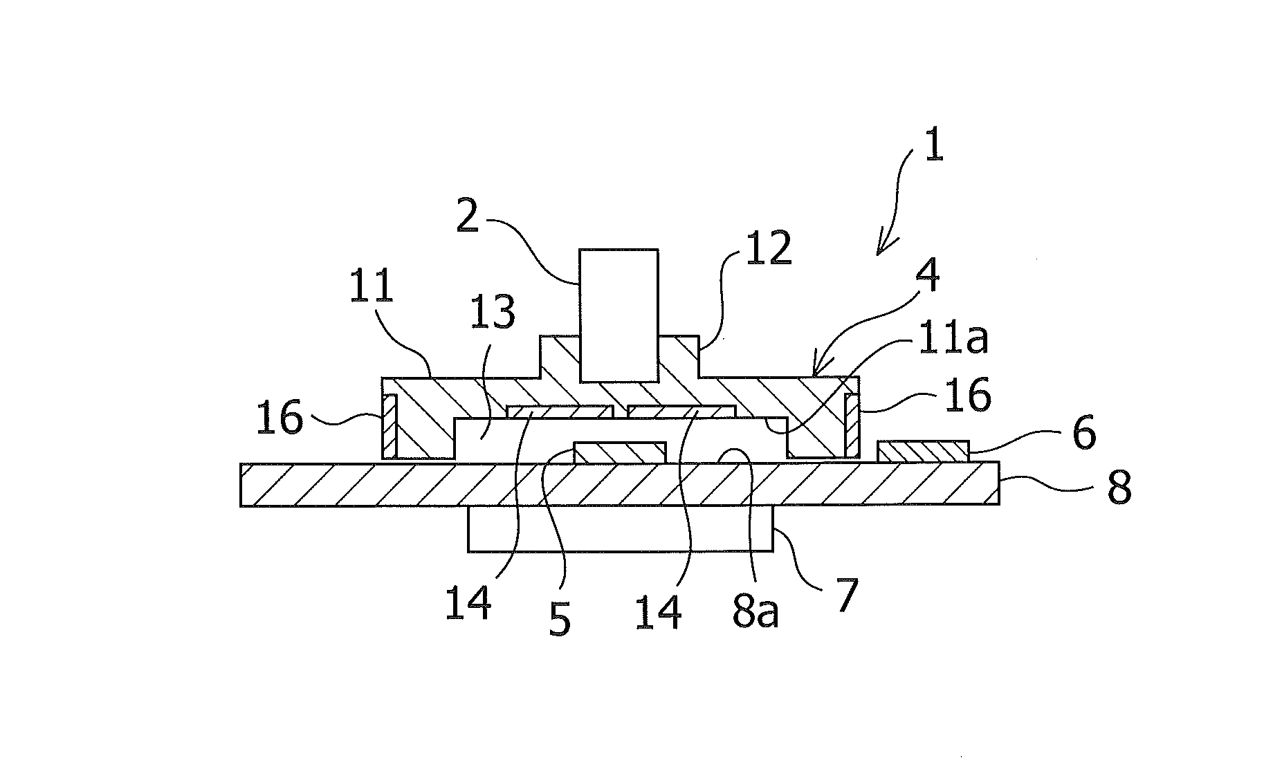
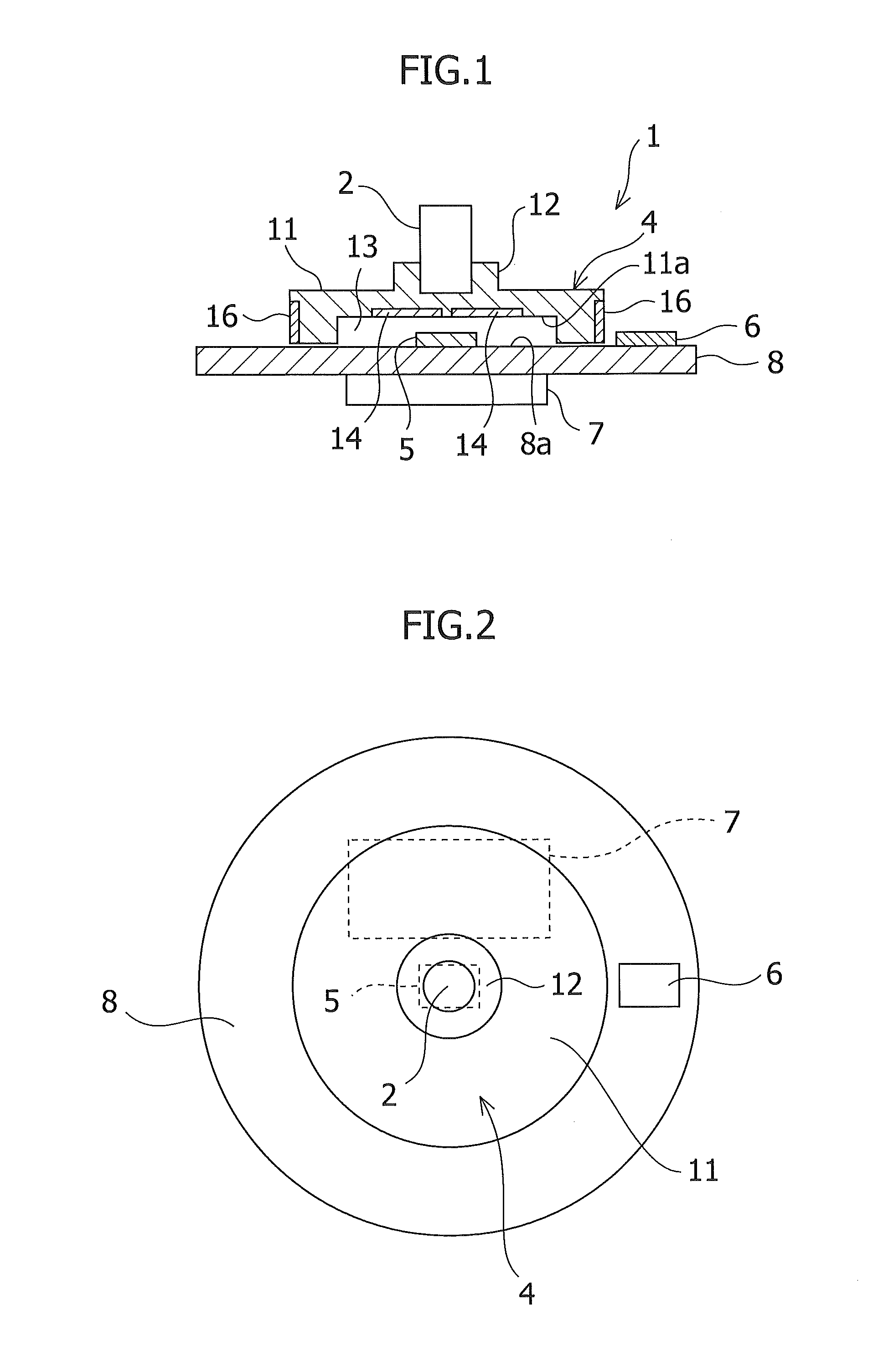
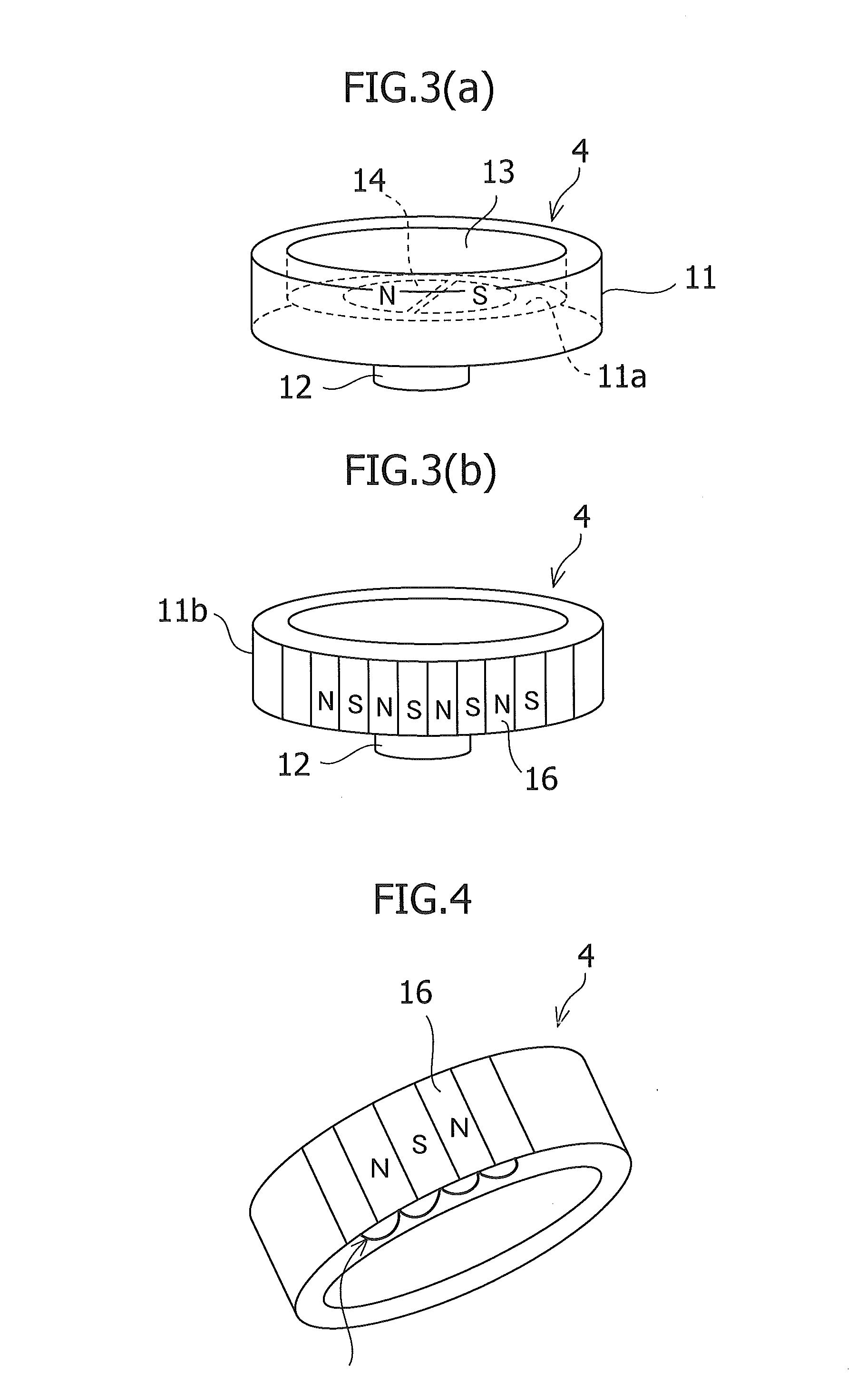
[0052]Now, embodiments of the present invention are described with reference to the attached drawings. FIG. 1 is a cross-sectional view of an absolute encoder device according to a first embodiment of the present invention, and FIG. 2 is a plan view of the encoder device illustrated in FIG. 1 as viewed from above. An encoder device 1 includes a permanent magnet 4 fixed to a rotation shaft 2, and a substrate 8 for supporting a first magnetic sensor 5, a second magnetic sensor 6, and a signal processing circuit 7. The permanent magnet 4 includes a disc-like main body part 11 having a cup shape with an elongated protrusion formed along a peripheral rim on a lower side, and a rotation shaft fixing portion 12 protruding from a center part of a top surface of the main body part 11 toward the rotation shaft 2 with a step part. In this embodiment, a distal end of the rotation shaft 2 is inserted into a recess formed in a center axis of the rotation shaft fixing portion 12 of the permanent m...

second embodiment

[0078]FIG. 16 is a cross-sectional view of an absolute encoder device according to a second embodiment of the present invention, and FIG. 17 is a plan view of the encoder device illustrated in FIG. 16 as viewed from above. In an encoder device 31 illustrated in FIGS. 16 and 17, a component corresponding to the component of the encoder device 1 of the first embodiment is denoted by the same reference symbol as in the first embodiment. The encoder device 31 according to the second embodiment has a structure different from that of the encoder device 1 according to the first embodiment in that the rotation shaft 2 penetrates the substrate 8. The distal end of the rotation shaft 2 passes through a through hole 8b formed at a center of the substrate 8 and is inserted into a through hole 12a formed in the rotation shaft fixing portion 12 from inside of the permanent magnet 4 so as to be fixed to the permanent magnet 4 with a screw 32.

[0079]A configuration of the first magnetic pattern 14 o...


PUM


Abstract

The present invention provides an absolute encoder device, including: a permanent magnet including a first magnetic pattern (bipolar) and a second magnetic pattern (multipolar); a first magnetic sensor for detecting a magnetic field of the first magnetic pattern; a second magnetic sensor for detecting a magnetic field of the second magnetic pattern; and a signal processing circuit for calculating an absolute rotation angle of a rotation shaft based on output signals of the first and second magnetic sensors. The first and second magnetic sensors and the signal processing circuit are fixed to a single substrate. The first magnetic pattern is formed on a plane extending in a direction crossing an axial direction inside the permanent magnet, and the second magnetic pattern is formed on an outer peripheral surface of the permanent magnet.

Description

TECHNICAL FIELD[0001]The present invention relates to an absolute encoder device and a motor.BACKGROUND ART[0002]As a device for controlling rotation of a motor, there is known an absolute encoder device. The absolute encoder device can be used for, for example, detecting a rotation direction, a rotational frequency, or a rotational position of a motor. As this absolute encoder device, there are a magnetic type and an optical type. The magnetic type is less expensive than the optical type and is superior in environmental resistance.[0003]In the magnetic type absolute encoder device, for example, a magnetic sensor is arranged to be opposed to a bipolar permanent magnet fixed to a rotation shaft. As the magnetic sensor, there is known a sensor using a spin-valve giant magnetoresistive element (SV-GMR) as a magnetoresistive element (for example, see Patent Literature 1). The SV-GMR type magnetic sensor includes a pinned layer and a free layer. A pinned layer magnetization direction is ...

Claims


Application Information

Patent Timeline
IPC IPC(8): H02K11/00G01B7/30
CPCG01D5/145G01D5/2451H02K11/0021G01B7/30G01D5/2454H02K11/215G01D5/245H02K11/00
Inventor SOMEYA, MASAYUKIHIRASAWA, YOSHIOOZEKI, SAKAO
Owner ORIENTAL MOTOR
Why Eureka
Try Eureka