Circuit board and heat dissipation device thereof

a heat dissipation device and circuit board technology, applied in the direction of cross-talk/noise/interference reduction, printed circuit aspects, electrical apparatus construction details, etc., can solve the problems of device receiving high-frequency noise, device damage, and reduced working efficiency

Active Publication Date: 2014-01-16
WISTRON CORP
View PDF0 Cites 9 Cited by
  • Summary
  • Abstract
  • Description
  • Claims
  • Application Information

AI Technical Summary

Benefits of technology

[0011]One of the characteristics of the present invention lies in that, a conductive element is additionally added to a heat dissipation device in the prior art, and the conductive element of the heat dissipation device is enabled to be connected electrically to a heat dissipation element and a bare metal area, so that the heat dissipation element is grounded, thereby resolving the electromagnetic interference problem resulting from that a high-frequency noise generated during the computation of a chip radiates out by using the heat dissipation element as an antenna.

Problems solved by technology

Processing chip power is becoming increasingly higher; accordingly, heat generated by the processing chips may be accumulated, resulting in internal elements being damaged, or working efficiency being reduced.
However, during operation a chip generates signals unexpected by a system or even signals adversely affecting the operation, and an adjacent heat dissipation device receives a high-frequency noise generated by the chip.
However, because of the disposition of the heat dissipation device, especially a heat dissipation fin, which is not conductively connected to a circuit board where the chip is located, the high-frequency noise generated by the chip is coupled to the heat dissipation fin and has no path for elimination.
Consequently, in a wireless transmission manner, the high-frequency noise radiates out by using the heat dissipation fin as an antenna.
As a result, adjacent electronic elements are subject to interference of the high-frequency noise, resulting in that the system is unstable or has unexpected problems.
However, after the heat dissipation devices are disposed, the high-frequency nose generated due to the high-clock operation of the chips is radiated to a surrounding environment by using the heat dissipation devices as antennas, and an electromagnetic interference problem arises spontaneously.
In conclusion, the circuit boards and the heat dissipation devices thereof in the prior art have an electromagnetic interference problem resulting from that high-frequency noise generated during a high-speed operation of chips, radiates out through heat dissipation elements.

Method used


Image

  • Circuit board and heat dissipation device thereof
  • Circuit board and heat dissipation device thereof
  • Circuit board and heat dissipation device thereof

Examples


Embodiment Construction

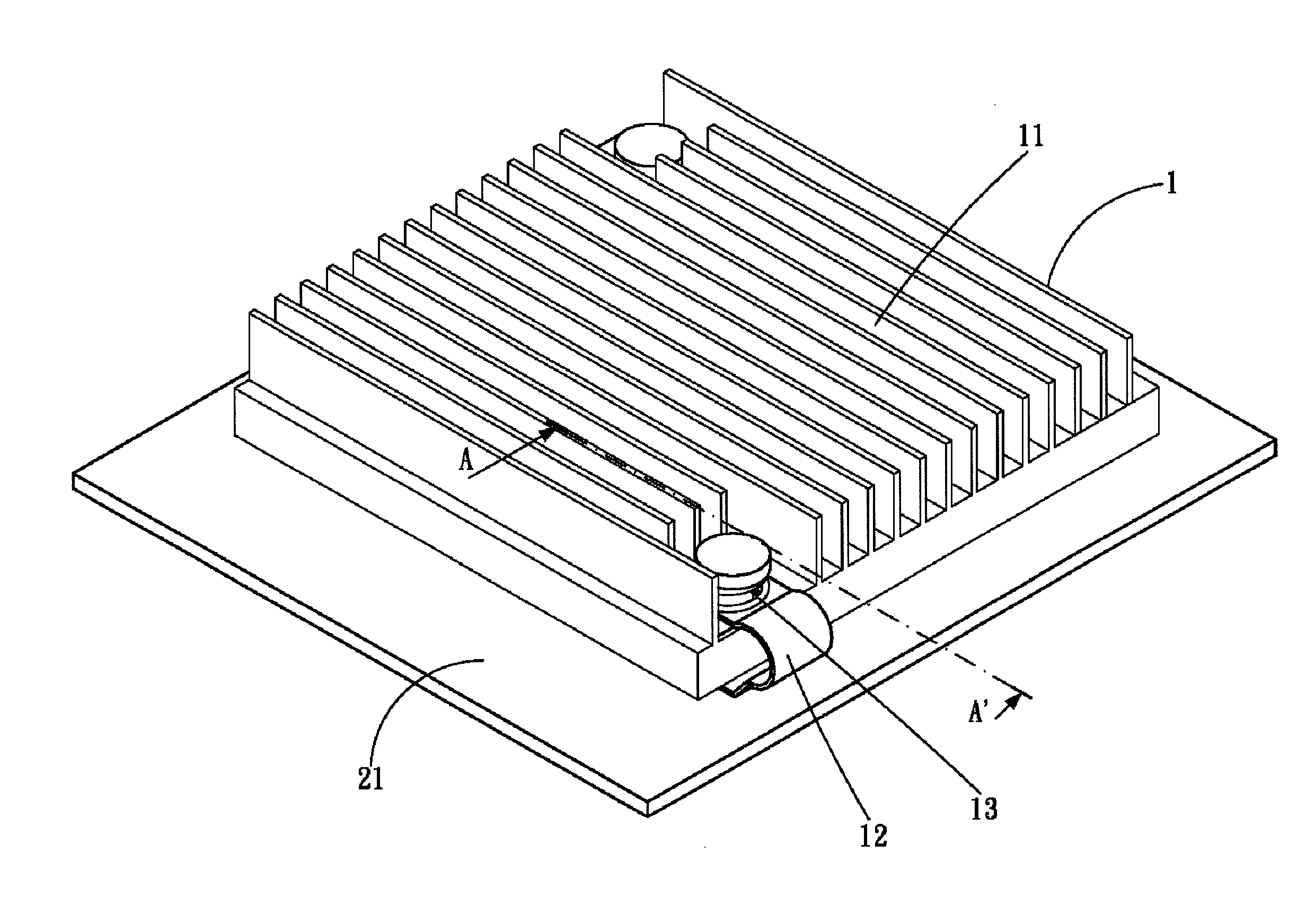
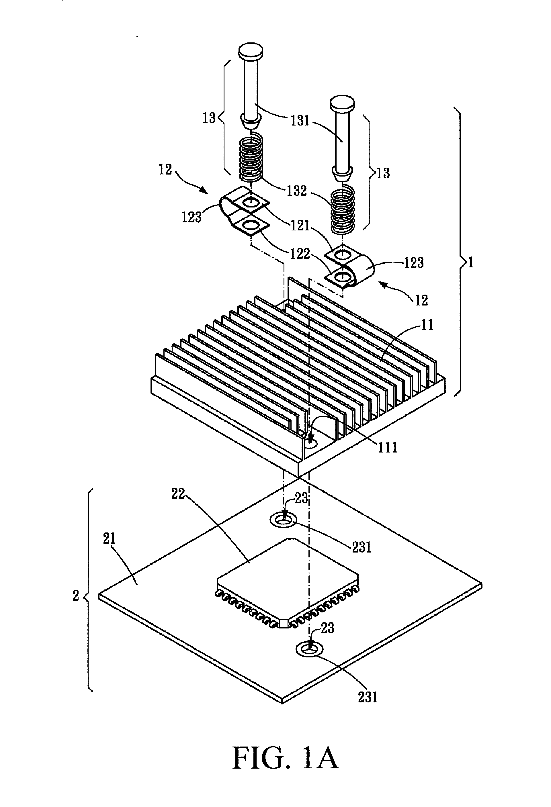
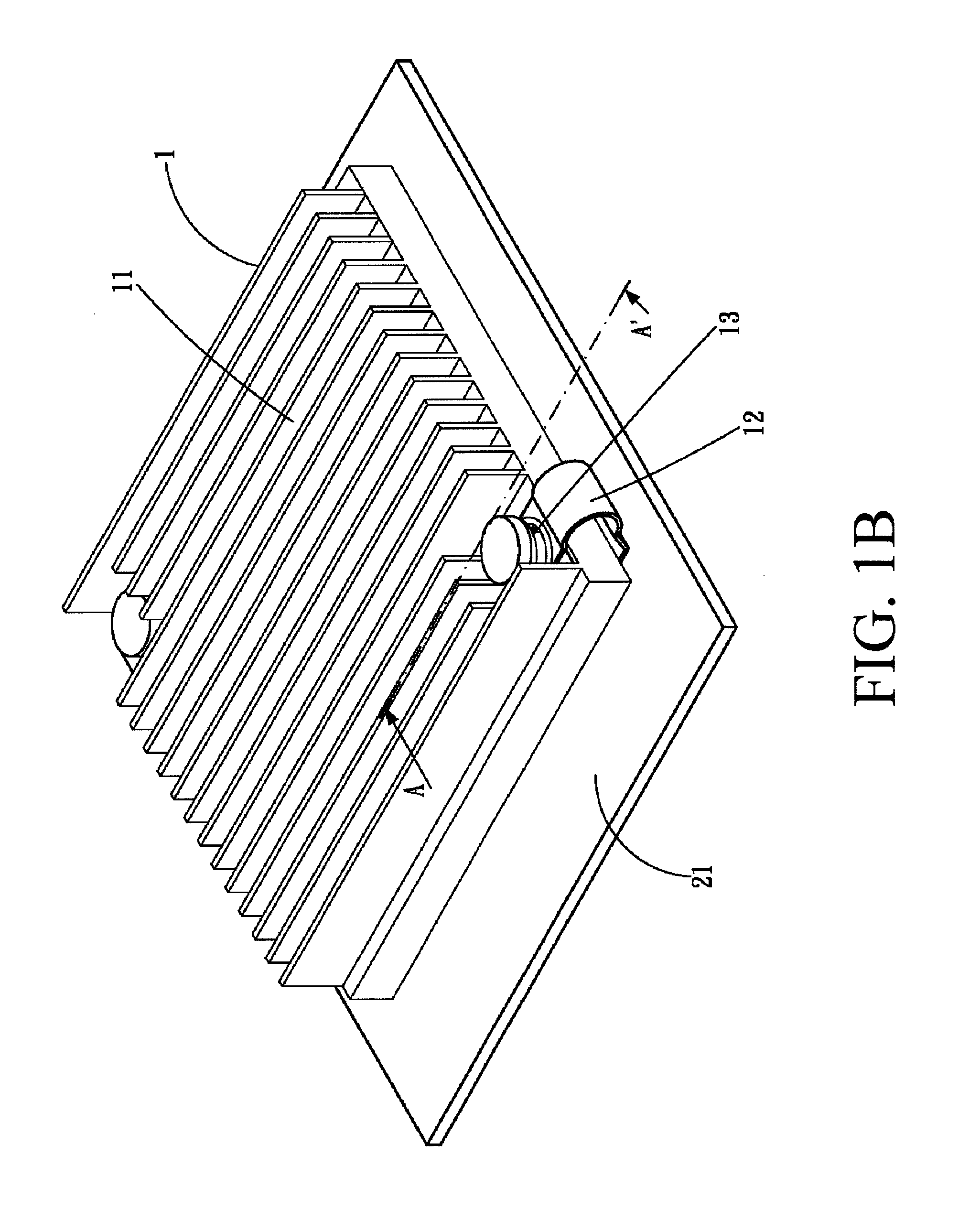
[0023]FIGS. 1A to 1C are respectively an explosive view of a first embodiment of the present invention, an assembly view of the first embodiment of the present invention, and a sectional view along a section line AA′ of FIG. 1B. Please refer to FIGS. 1A to 1C, in which a heat dissipation device 1 is provided, used in a circuit board 2. The circuit board 2 includes a substrate 21, a chip 22, and at least one positioning hole 23. Each of the positioning holes 23 is disposed around the chip 22, and each of the positioning holes 23 has a bare metal area 231 on its periphery. The heat dissipation device 1 includes a heat dissipation element 11, a conductive element 12 and at least one fixing part 13.

[0024]The heat dissipation element 11 is disposed on the chip 22, and contacts with the chip 22 face to face to receive heat generated during high-speed computation of the chip 22. The heat dissipation element 11 has multiple heat dissipation fins on the other surface with respect to a contac...


PUM


Abstract

A heat dissipation device is used in a circuit board, where the circuit board includes a chip and at least one positioning hole disposed around the chip, and each of the positioning holes has a bare metal area on its periphery. The heat dissipation device includes a heat dissipation element, a conductive element and at least one fixing part. The heat dissipation element is disposed on the chip; the conductive element is connected electrically to the bare metal area of the circuit board and the heat dissipation element respectively; the fixing part passes through the fixing holes and is connected to the positioning hole, so as to fix the heat dissipation element to the circuit board. A circuit board is also provided, which includes a substrate, a chip, a positioning hole and the heat dissipation device.

Description

CROSS-REFERENCES TO RELATED APPLICATIONS[0001]This non-provisional application claims priority under 35 U.S.C. §119(a) on patent application No. 101125345 filed in Taiwan, R.O.C. on Jul. 13, 2012, the entire contents of which are hereby incorporated by reference.BACKGROUND OF THE INVENTION[0002]1. Technical Field[0003]The present invention relates to a circuit board and a heat dissipation device thereof.[0004]2. Related Art[0005]With the continuous development of technologies, the present consumer electronic products have a more and more intensive process due to an increasingly growing working clock of processing chips (CPU / Scalar). Processing chip power is becoming increasingly higher; accordingly, heat generated by the processing chips may be accumulated, resulting in internal elements being damaged, or working efficiency being reduced. In the prior art, heat dissipation devices are additionally disposed on processing chips, and the heat accumulation problem of the processing chip...

Claims


Application Information

Patent Timeline
Patent Type & Authority Applications(United States)
IPC IPC(8): H05K7/20
CPCH01L23/4093H05K1/0203H05K2201/09063H01L2924/0002H01L2924/00H01L23/4006H01L23/552H05K1/0216
Inventor CHIANG, YU-FENGLEE, CHENG-HAOWANG, CHUN-LINKUO, TUNG-HUANG
Owner WISTRON CORP
Why Eureka
Try Eureka