
HDMI signal adjusting method, HDMI signal receiving apparatus, HDMI signal transmitting apparatus, and HDMI signal processing system

a signal processing system and signal processing technology, applied in the field of high definition multimedia interface (hdmi) signal processing, can solve the problems of difficult noise removal during, noise and signal leakage becoming more serious, and achieve the effect of optimal signal exchanging environment and easy adjustment of signal

Inactive Publication Date: 2014-01-16
SAMSUNG ELECTRONICS CO LTD
View PDF9 Cites 9 Cited by
  • Summary
  • Abstract
  • Description
  • Claims
  • Application Information

AI Technical Summary

Benefits of technology

The patent describes a method for easily adjusting the signal when connecting HDMI devices. The method provides an automatic signal adjusting function, so that users don't have to manually set the optimal signal exchanging environment. This results in improved signal quality and reduced resolution deterioration. Overall, the method simplifies and streamlines the process of setting up an HDMI system.

Problems solved by technology

However, it is difficult to discriminate between noise and a signal in the band of 300-600 Mhz, and thus, there is a problem that it is difficult to remove noise during the transmission of an HDMI signal.
Further, if there is a problem in connecting an HDMI cable or if the cable is overly elongated, the problems of noise and signal leakage become more serious.
However, since the problems of noise and signal leakage become more serious according to a connection state of the HDMI cable as described above, it is necessary to adjust the HDMI signal considering a setting environment of an HDMI apparatus.
However, it is understood that one or more exemplary embodiments are not required to overcome the disadvantages described above, and may not overcome any of the problems described above.

Method used


Image

  • HDMI signal adjusting method, HDMI signal receiving apparatus, HDMI signal transmitting apparatus, and HDMI signal processing system
  • HDMI signal adjusting method, HDMI signal receiving apparatus, HDMI signal transmitting apparatus, and HDMI signal processing system
  • HDMI signal adjusting method, HDMI signal receiving apparatus, HDMI signal transmitting apparatus, and HDMI signal processing system

Examples


Embodiment Construction

[0054]Hereinafter, exemplary embodiments will be described in greater detail with reference to the accompanying drawings.

[0055]In the following description, the same reference numerals are used for the same elements when they are depicted in different drawings. The matters defined in the description, such as a detailed construction and elements, are provided to assist in a comprehensive understanding of exemplary embodiments. Thus, it is apparent that exemplary embodiments can be carried out without those specifically defined matters. Also, functions or elements known in the related art are not described in detail since they would obscure the exemplary embodiments with unnecessary detail.

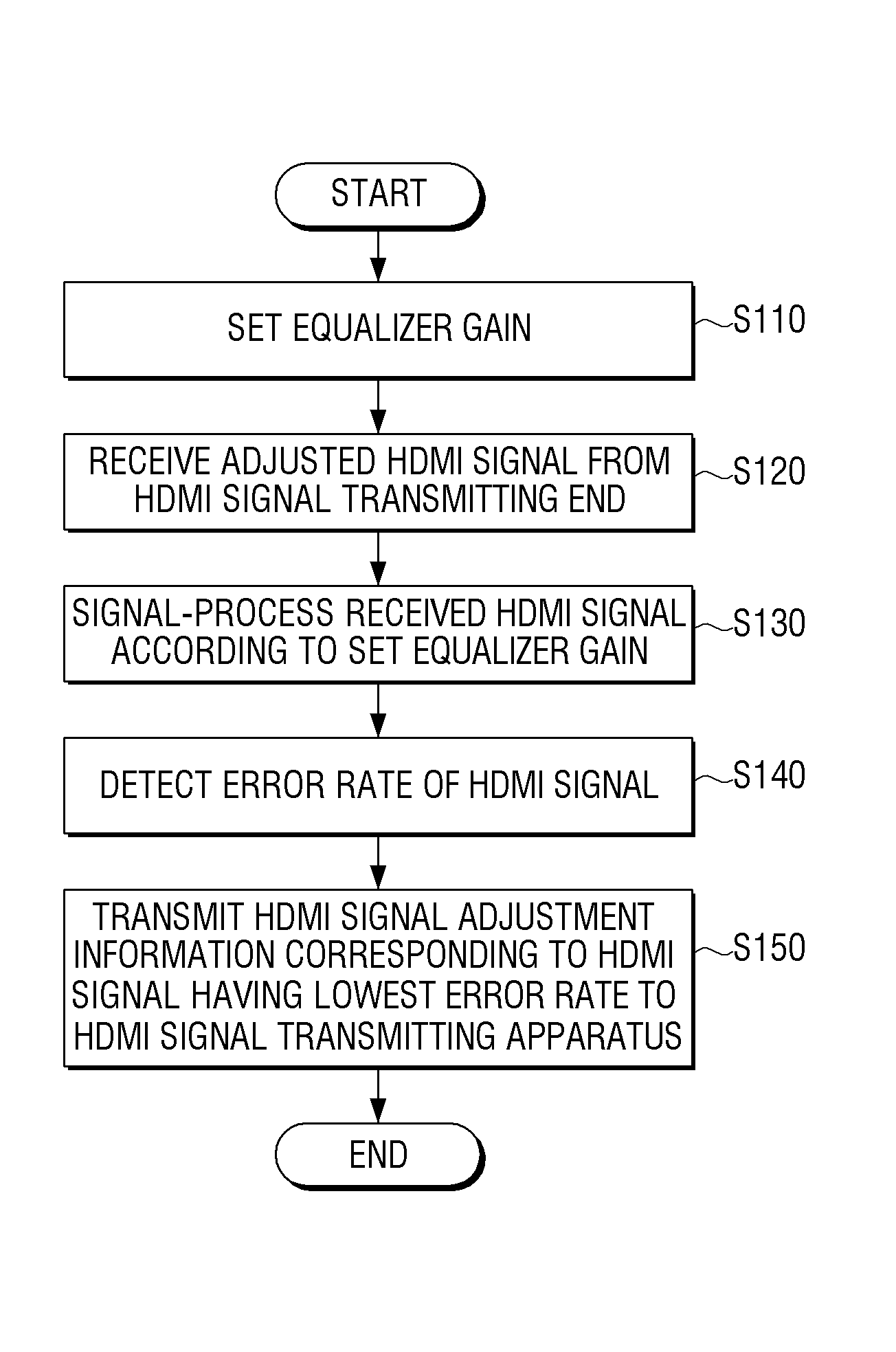
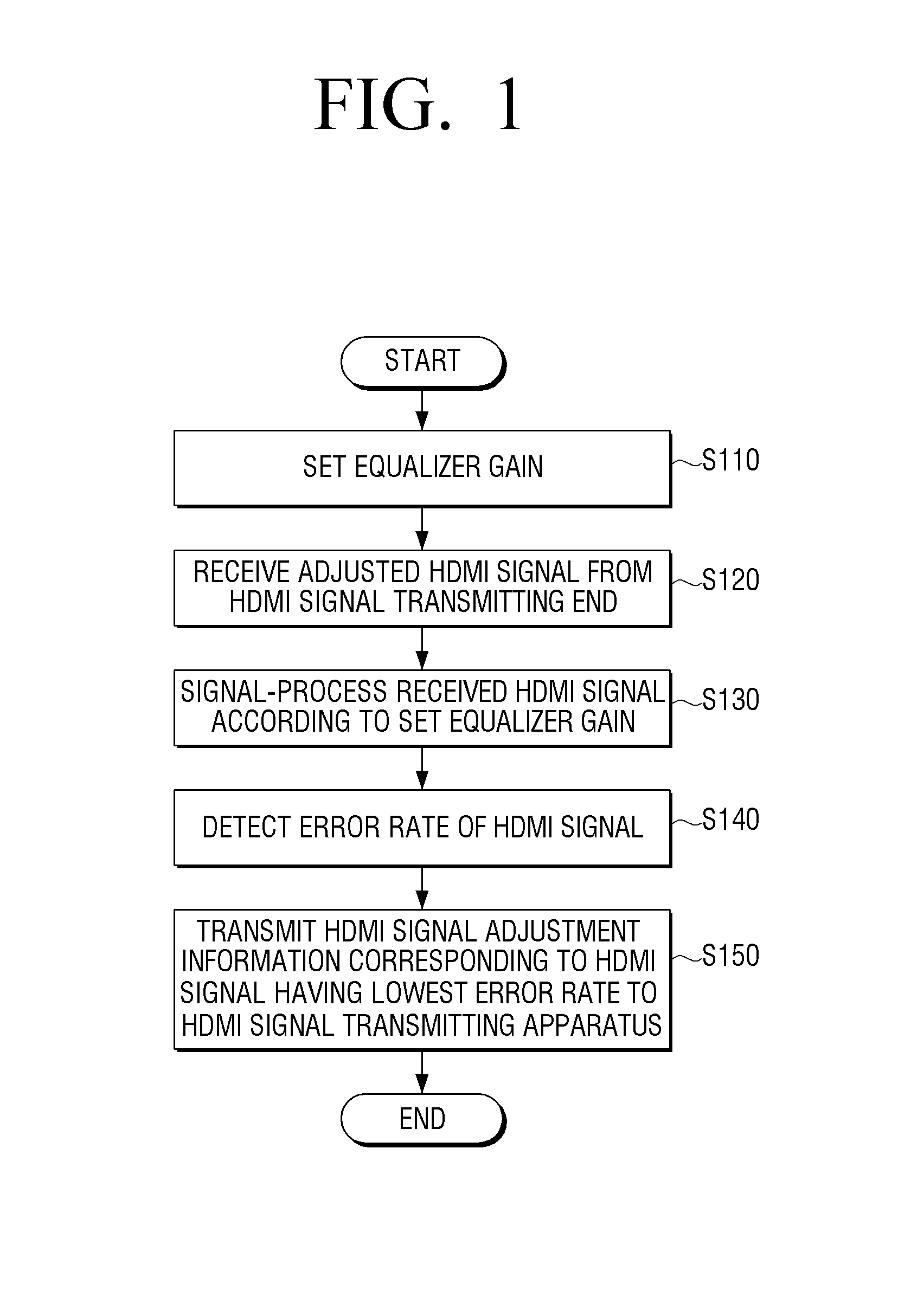
[0056]FIG. 1 is a flowchart illustrating an HDMI signal adjusting method according to an exemplary embodiment.

[0057]Referring to FIG. 1, the HDMI signal adjusting method according to an exemplary embodiment includes setting an equalizer gain at operation S110, receiving an HDMI signal which is adjus...


PUM


Abstract

An HDMI signal adjusting method is provided. A method for adjusting an HDMI signal of a high definition multimedia interface (HDMI) signal receiving apparatus includes: setting an equalizer gain for an HDMI signal, receiving an HDMI signal which is adjusted according to signal adjustment information set by an HDMI signal transmitting apparatus from the HDMI signal transmitting apparatus, signal-processing the received HDMI signal according to the set equalizer gain, detecting an error rate of the signal-processed HDMI signal, and transmitting signal adjustment information corresponding to an HDMI signal having a lowest error rate from among a plurality of the signal-processed HDMI signals corresponding to a plurality of different combinations of the equalizer gain and the signal adjustment information to the HDMI signal transmitting apparatus.

Description

CROSS-REFERENCE TO RELATED APPLICATION[0001]This application claims priority from Korean Patent Application No. 10-2012-0075185, filed on Jul. 10, 2012, in the Korean Intellectual Property Office, the disclosure of which is incorporated herein by reference in its entirety.BACKGROUND[0002]1. Field[0003]Methods and apparatuses consistent with exemplary embodiments relate to high definition multimedia interface (HDMI) signal processing, and more particularly, to an HDMI signal adjusting method which adjusts a signal of an HDMI apparatus, an HDMI signal receiving apparatus, an HDMI signal transmitting apparatus, and an HDMI signal processing system.[0004]2. Description of the Related Art[0005]HDMI is a digital video / audio interface standard which uses a non-compression method. HDMI provides an interface between a multimedia source which supports HDMI, such as a set-top box or a digital versatile disk (DVD) player, and an apparatus such as an (audio / video) AV apparatus, a monitor, or a d...

Claims


Application Information

Patent Timeline
Patent Type & Authority Applications(United States)
IPC IPC(8): H04L27/01
CPCH04L27/01G09G5/006G09G2370/00G09G2370/08G09G2370/12H04N5/44
Inventor HONG, SEUNG-SESEO, YOUNG-JOOH, SUNG-BOLIM, JUN-HOJEON, HYOUNG-WOOCHA, KI-SUNG
Owner SAMSUNG ELECTRONICS CO LTD
Learn More