
Heat-distribution indicators, thermal zone indicators, electrosurgical systems including same and methods of directing energy to tissue using same

a technology of electrosurgical system and indicator, which is applied in the field of system, device and method of performing a medical procedure, can solve the problems of unfavorable patient safety, unfavorable patient safety, and damage to surrounding tissue, so as to improve patient outcomes, improve patient safety, and reduce risk

Inactive Publication Date: 2014-01-16
TYCO HEALTHCARE GRP LP
View PDF3 Cites 46 Cited by
  • Summary
  • Abstract
  • Description
  • Claims
  • Application Information

AI Technical Summary

Benefits of technology

The patent text describes the need for systems, devices, and methods to control and monitor real-time tissue effects to improve patient safety and outcomes. Specifically, there is a need for intraoperative techniques to assess ablation margin and feedback control. The technical effect of this patent is to provide a solution for addressing this need.

Problems solved by technology

Using electrosurgical instruments to ablate, seal, cauterize, coagulate, and / or desiccate tissue may result in some degree of thermal injury to surrounding tissue.
For example, electrosurgical desiccation may result in undesirable tissue damage due to thermal effects, wherein otherwise healthy tissue surrounding the tissue to which the electrosurgical energy is being applied is thermally damaged by an effect known in the art as “thermal spread”.
During the occurrence of thermal spread, excess heat from the operative site can be directly conducted to the adjacent tissue and / or the release of steam from the tissue being treated at the operative site can result in damage to the surrounding tissue.
As can be appreciated, limiting the possibility of thermal spread or the like during an electrosurgical procedure reduces the likelihood of unintentional and / or undesirable collateral damage to surrounding tissue structures which may be adjacent to an intended treatment site.

Method used


Image

  • Heat-distribution indicators, thermal zone indicators, electrosurgical systems including same and methods of directing energy to tissue using same
  • Heat-distribution indicators, thermal zone indicators, electrosurgical systems including same and methods of directing energy to tissue using same
  • Heat-distribution indicators, thermal zone indicators, electrosurgical systems including same and methods of directing energy to tissue using same

Examples


Embodiment Construction

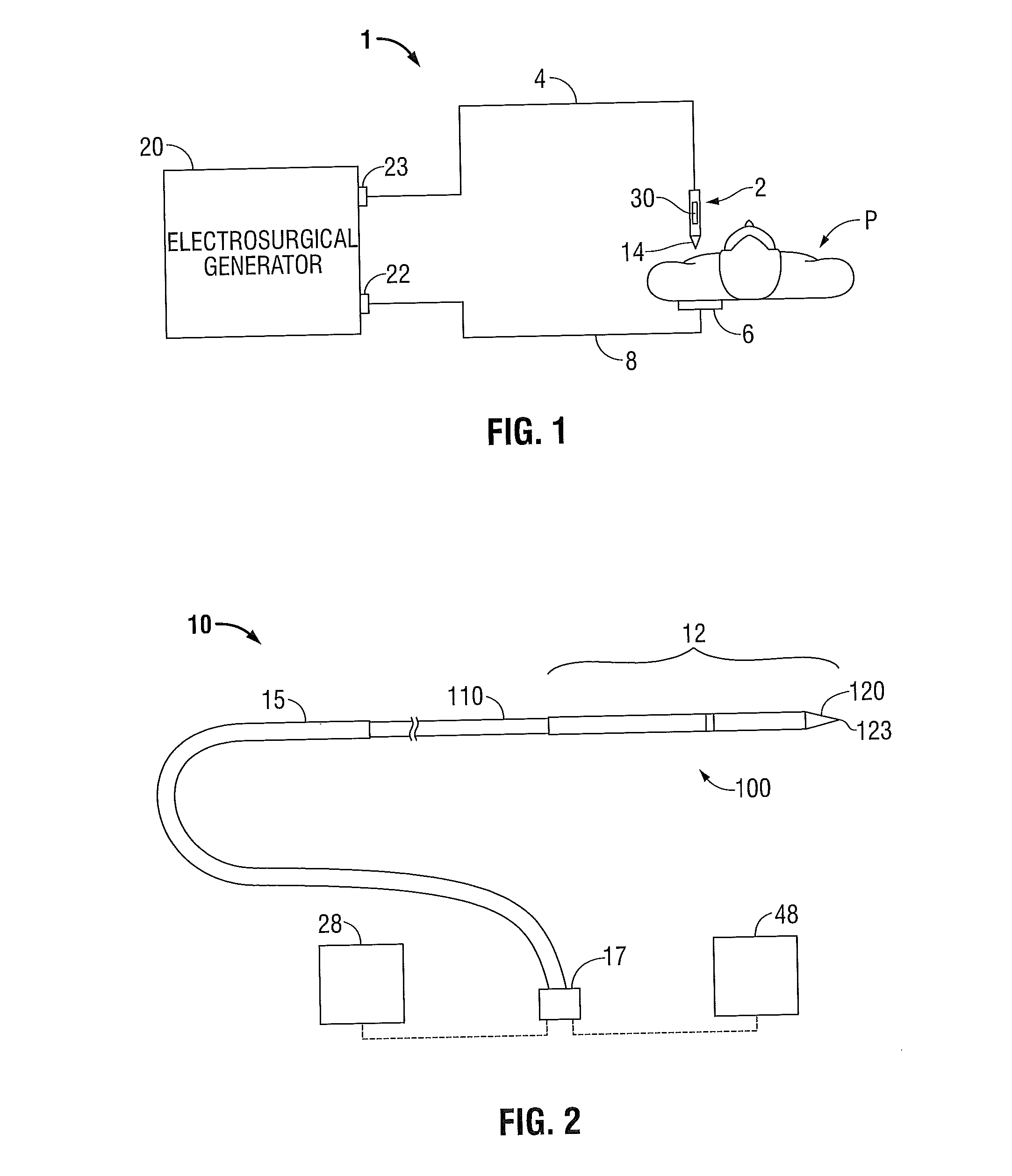
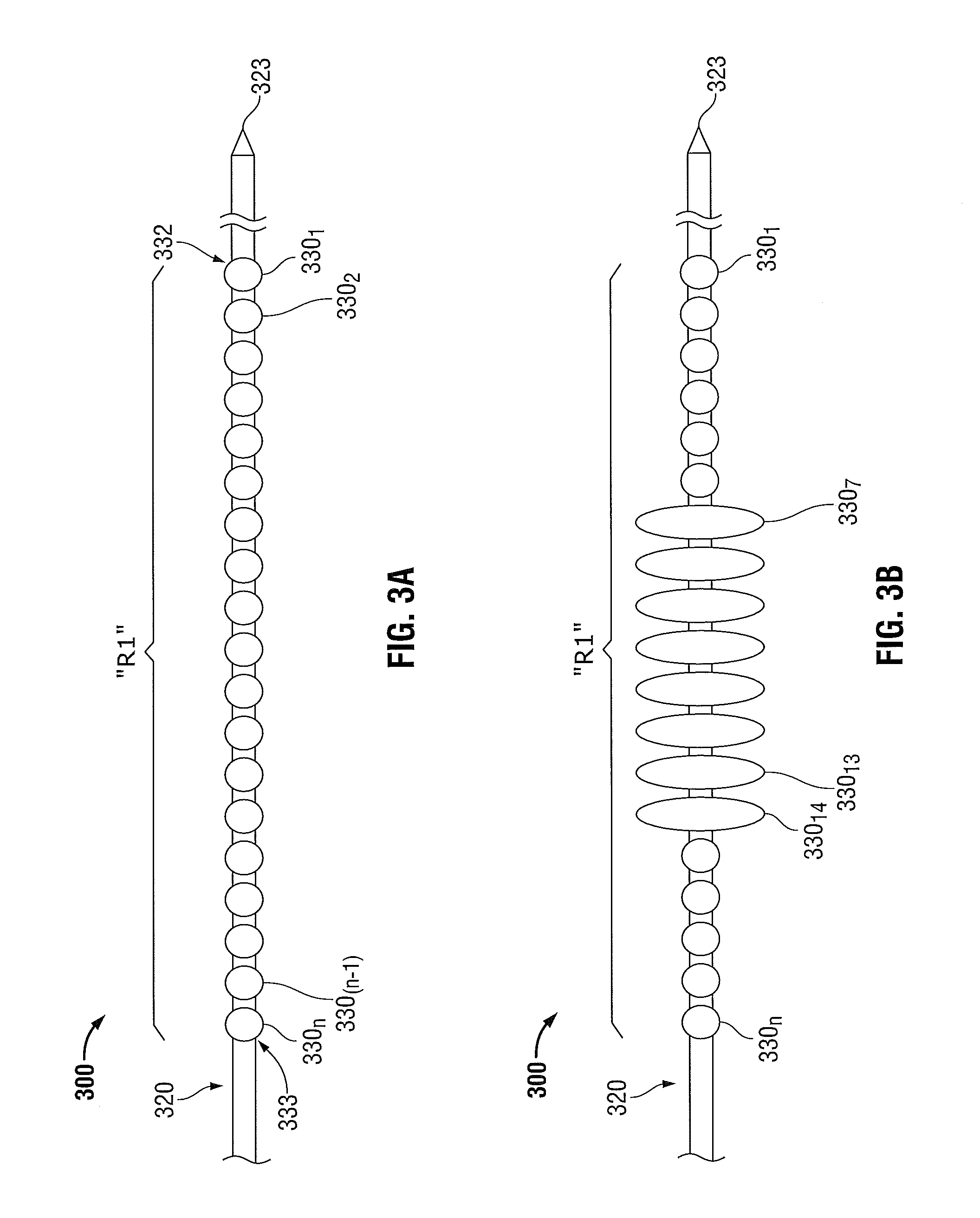
[0050]Hereinafter, embodiments of the presently-disclosed heat-distribution indicators, thermal zone indicators, electrosurgical devices including the same, and systems and methods for directing energy to tissue are described with reference to the accompanying drawings. Like reference numerals may refer to similar or identical elements throughout the description of the figures. As shown in the drawings and as used in this description, and as is traditional when referring to relative positioning on an object, the term “proximal” refers to that portion of the device, or component thereof, closer to the user and the term “distal” refers to that portion of the device, or component thereof, farther from the user.

[0051]This description may use the phrases “in an embodiment,”“in embodiments,”“in some embodiments,” or “in other embodiments,” which may each refer to one or more of the same or different embodiments in accordance with the present disclosure.

[0052]Electromagnetic energy is gene...


PUM


Abstract

An electrosurgical system includes an electrosurgical power generating source, an energy applicator operably associated with the electrosurgical power generating source, a heat-distribution indicator adapted to change echogenic properties in response to heat generated by energy delivered by the energy applicator, and a processor unit configured to generate at least one electrical signal for controlling at least one operating parameter associated with the electrosurgical power generating source. The system also includes an imaging system capable of acquiring image data. The imaging system is communicatively-coupled to the processor unit. The processor unit is adapted to determine an ablation rate at least in part based on analysis of one or more images acquired by the imaging system.

Description

CROSS REFERENCE TO RELATED APPLICATION[0001]The present application claims the benefit of and priority to U.S. Provisional Application Ser. No. 61 / 670,986, filed on Jul. 12, 2012, the entire contents of which are incorporated herein by reference.BACKGROUND[0002]1. Technical Field[0003]The present disclosure relates to systems, devices and methods for performing a medical procedure. More particularly, the present disclosure relates to heat-distribution indicators and thermal zone indicators suitable for use during thermal ablation, electrosurgical systems including the same, and methods of directing energy to tissue using the same.[0004]2. Discussion of Related Art[0005]Electrosurgery is the application of electricity and / or electromagnetic energy to cut, dissect, ablate, coagulate, cauterize, seal or otherwise treat biological tissue during a surgical procedure. When electrical energy and / or electromagnetic energy is introduced to tissue, the energy-tissue interaction produces excit...

Claims


Application Information

Patent Timeline
IPC IPC(8): A61B5/00A61B18/14
CPCA61B5/4848A61B18/14A61B18/1815A61B2018/1861A61B2018/1869A61B2018/00702A61B2018/00714A61B2018/0072A61B2018/00726A61B2018/00755A61B2018/00767A61B2018/00791A61B2018/00797A61B2090/378A61B2090/3925A61B18/1477A61B90/37
Inventor SHARONOV, ALEXEY
Owner TYCO HEALTHCARE GRP LP
Learn More