Mouse trap with guillotine killing mechanism

a technology of guillotine and trap, which is applied in the field of mouse traps, can solve the problems of unsanitary and dangerous traps, unsanitary traps, and unsanitary traps, and achieve the effects of convenient disposal, simple construction and small siz

Active Publication Date: 2014-01-23
WOODSTREAM CORP
View PDF42 Cites 19 Cited by
  • Summary
  • Abstract
  • Description
  • Claims
  • Application Information

AI Technical Summary

Benefits of technology

[0008]The mouse trap of this invention can be reusable and preferably made of durable plastic, has a relatively simple construction, and is relatively small in size. The mechanics and physical structure of the mouse trap conceal the body of an expired rodent from view and allow for easy disposal.
[0009]Accordingly, it is an object of the present invention to provide a mouse trap having a guillotine killing mechanism that efficiently kills a rodent and does not expose people and pets to any risk of injury or sickness from contact with the dispatched mouse or the trap.
[0010]A further object of the present invention is to provide a mouse trap in accordance with the preceding objects that is simple to set and use and which requires no electrical parts.
[0011]Yet another object of the present invention is to provide a mouse trap in accordance with the preceding objects that is sturdy and reusable in both indoor and outdoor environments.
[0012]It is yet another object of the invention to provide a mouse trap that is not complex in structure and which can be manufactured at low cost but yet efficiently kills and conceals an expired rodent from view until disposal thereof.

Problems solved by technology

Current methods of capturing and / or killing rodents such as mice are unsightly, unsanitary and can be dangerous.
However, the sight of the dead rodent caught in the trap is not pleasant and it may spread bacteria in the area around the trap.
These types of traps are also dangerous because they may injure children or family pets.
This method is not conducive to use within the home where people and pets may unknowingly handle the poison.
Poison left outside the home may also kill harmless wild animals.
The use of poisons may also lead to rodents expiring in undesirable areas or areas that are inaccessible, which will prevent proper disposal.
These methods are also undesirable because the enclosure must typically be larger in size in order to capture and contain the rodent and creating the burden of having to dispose of the live animal.

Method used


Image

  • Mouse trap with guillotine killing mechanism
  • Mouse trap with guillotine killing mechanism
  • Mouse trap with guillotine killing mechanism

Examples


Embodiment Construction

[0054]Although only one embodiment of the invention is explained in detail, it is to be understood that the invention is not limited in its scope to the details of construction and arrangement of components set forth in the following description or illustrated in the drawings. The invention is capable of other embodiments and of being practiced or carried out in various ways.

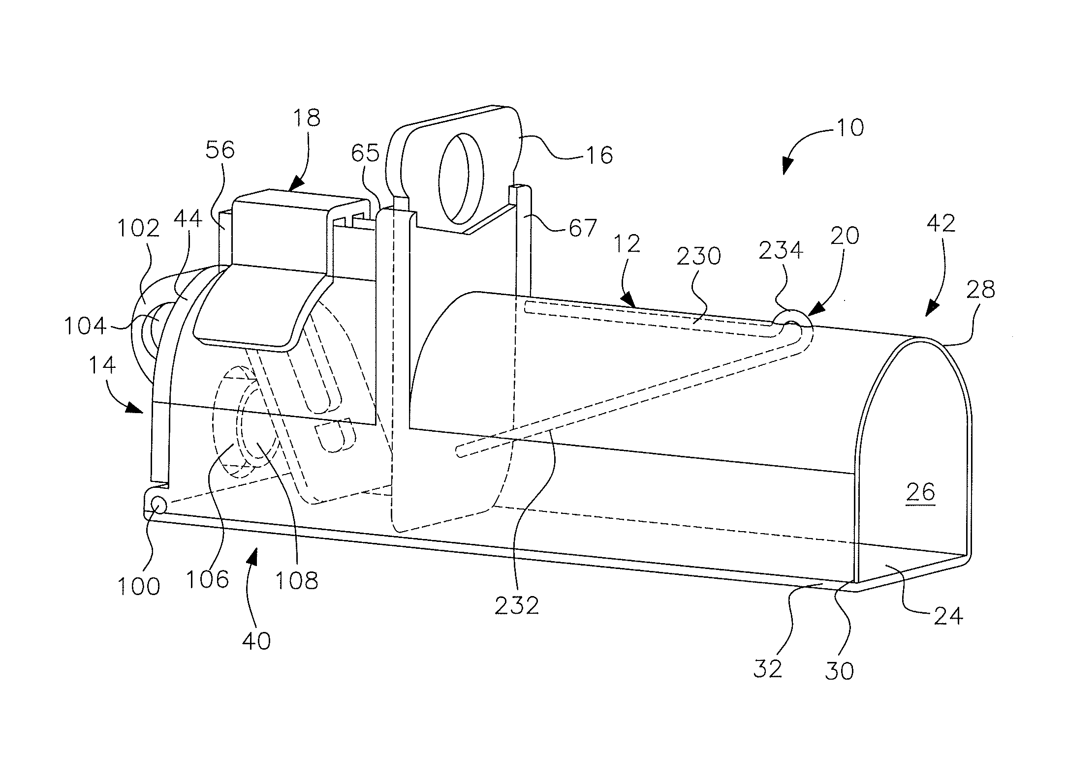
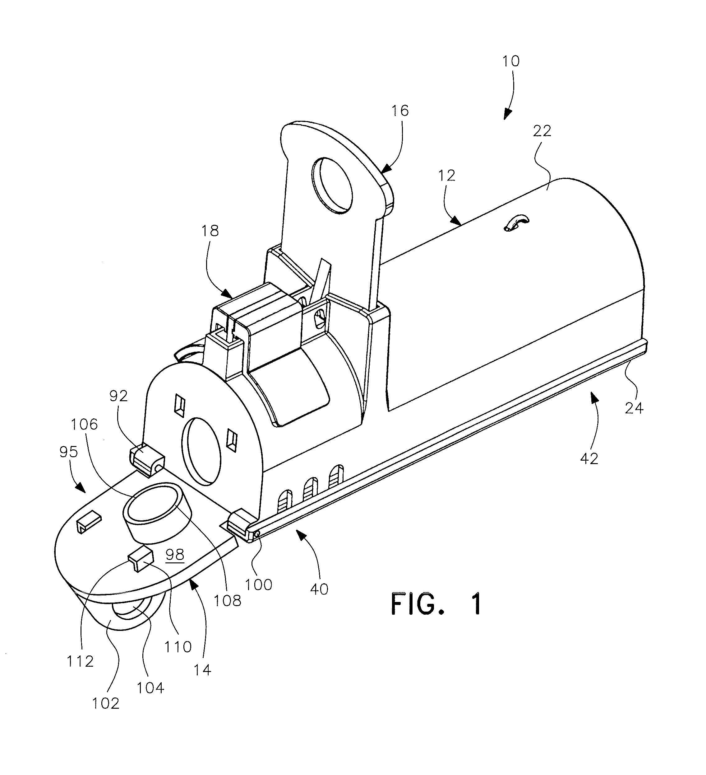
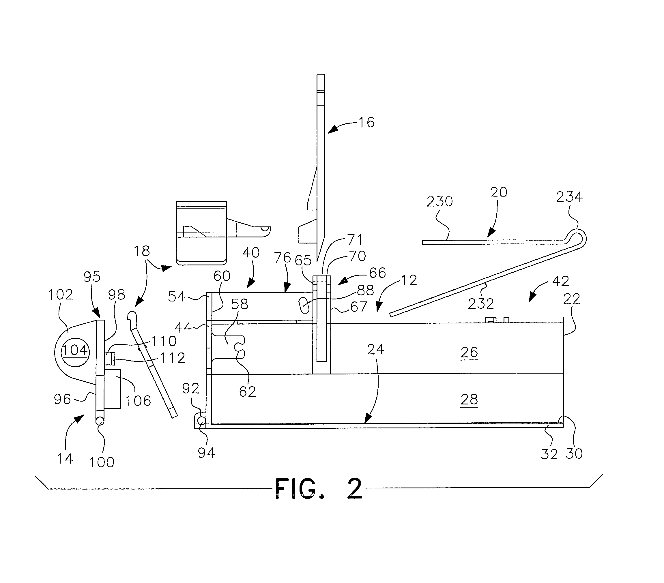
[0055]The present invention and related disclosure is directed to an improved mouse trap that is strong, relatively small, and reusable. The mouse trap also conceals the expired mouse within the trap and allows for quick and easy disposal without the need to come in contact with or handle the rodent. The mouse trap is preferably made of durable plastic but can be made out of any other suitably strong and rigid material.

[0056]As shown in FIGS. 1-5, 6A-6C, 7A-7C and 8A-8B, the present invention is directed to a mousetrap, generally designated by reference numeral 10. The mousetrap includes a housing generally desi...


PUM


Abstract

A mouse trap having a guillotine killing mechanism is provided. The trap includes a housing with a door, a guillotine positioned to extend at least partly into an interior of said housing, a trigger mechanism including a lever and catch to hold the guillotine in a raised position to set the trap, and a spring for biasing the guillotine to a lowered killing position when the trigger mechanism is activated to release the guillotine from the raised position.

Description

RELATED APPLICATIONS[0001]This application is based on U.S. Provisional Application Ser. No. 61 / 672,870, and hereby claims the priority thereof to which it is entitled.FIELD OF THE INVENTION[0002]The present invention is in the field of pest control and more specifically is directed to a mouse trap.BACKGROUND OF THE INVENTION[0003]Current methods of capturing and / or killing rodents such as mice are unsightly, unsanitary and can be dangerous. One example of such a method is the common mouse trap with a spring operated mechanism that is released by a trigger. The trigger is actuated when a mouse attempts to remove the bait secured thereto. The spring operated mechanism snaps closed, instantly killing the rodent. The entire trap with the expired rodent is disposable. However, the sight of the dead rodent caught in the trap is not pleasant and it may spread bacteria in the area around the trap. These types of traps are also dangerous because they may injure children or family pets.[0004...

Claims


Application Information

Patent Timeline
Patent Type & Authority Applications(United States)
IPC IPC(8): A01M23/36A01M27/00
CPCA01M23/36A01M27/00A01M23/16A01M23/20A01M23/24
Inventor SMITH, MATTHEW A.
Owner WOODSTREAM CORP
Why Eureka
Try Eureka