Handheld Apparatus For Quantifying Component Features

a technology of component features and handheld devices, applied in the field of handheld devices, can solve the problems of difficult to precisely align handheld devices with features, inaccurate thickness measurement, and burden on the additional time required for precise manual alignment of handheld devices with objects to obtain each dimension, and achieve the effect of precise measurement of the distance between the sensor

Active Publication Date: 2014-01-23
COGNEX CORP
View PDF3 Cites 104 Cited by
  • Summary
  • Abstract
  • Description
  • Claims
  • Application Information

AI Technical Summary

Benefits of technology

[0012]In some embodiments the processor is further programmed to compare the light patterns projected to the light patterns in the obtained images to identify a distance between the sensor and the surface of the object from which the light reflects and to use the identified distance as part of a calculation to identify the at least one dimension. In some embodiments at

Problems solved by technology

One problem with known devices of this type is that a device user is required to position the device such that the projected pattern is oriented in a specific fashion with respect to the feature to be dimensioned.
If the device is not properly aligned, the thickness measurement will be inaccurate.
While aligning a light pattern with an object feature may seem to be a simple p

Method used


Image

  • Handheld Apparatus For Quantifying Component Features
  • Handheld Apparatus For Quantifying Component Features
  • Handheld Apparatus For Quantifying Component Features

Examples


Embodiment Construction

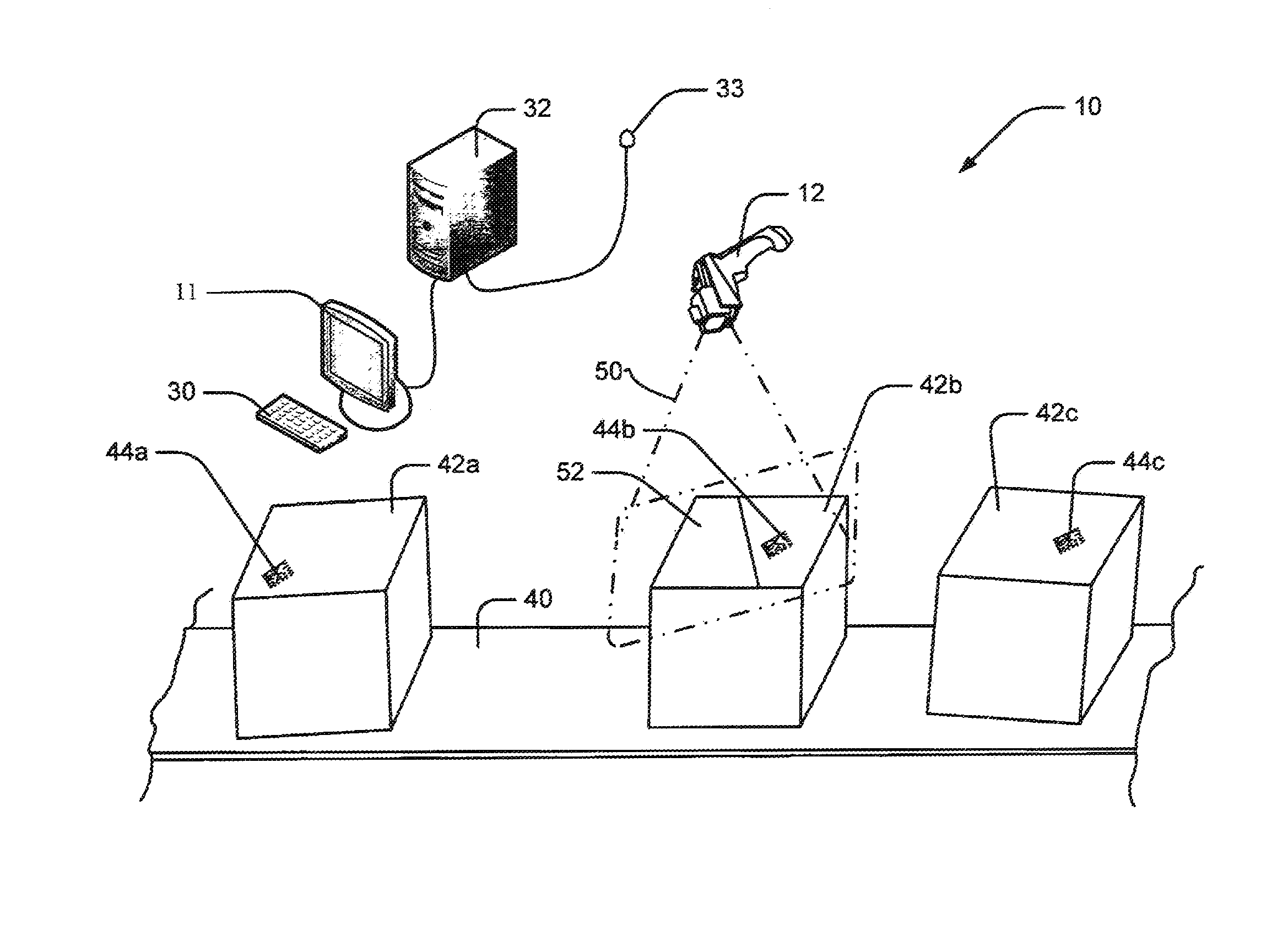
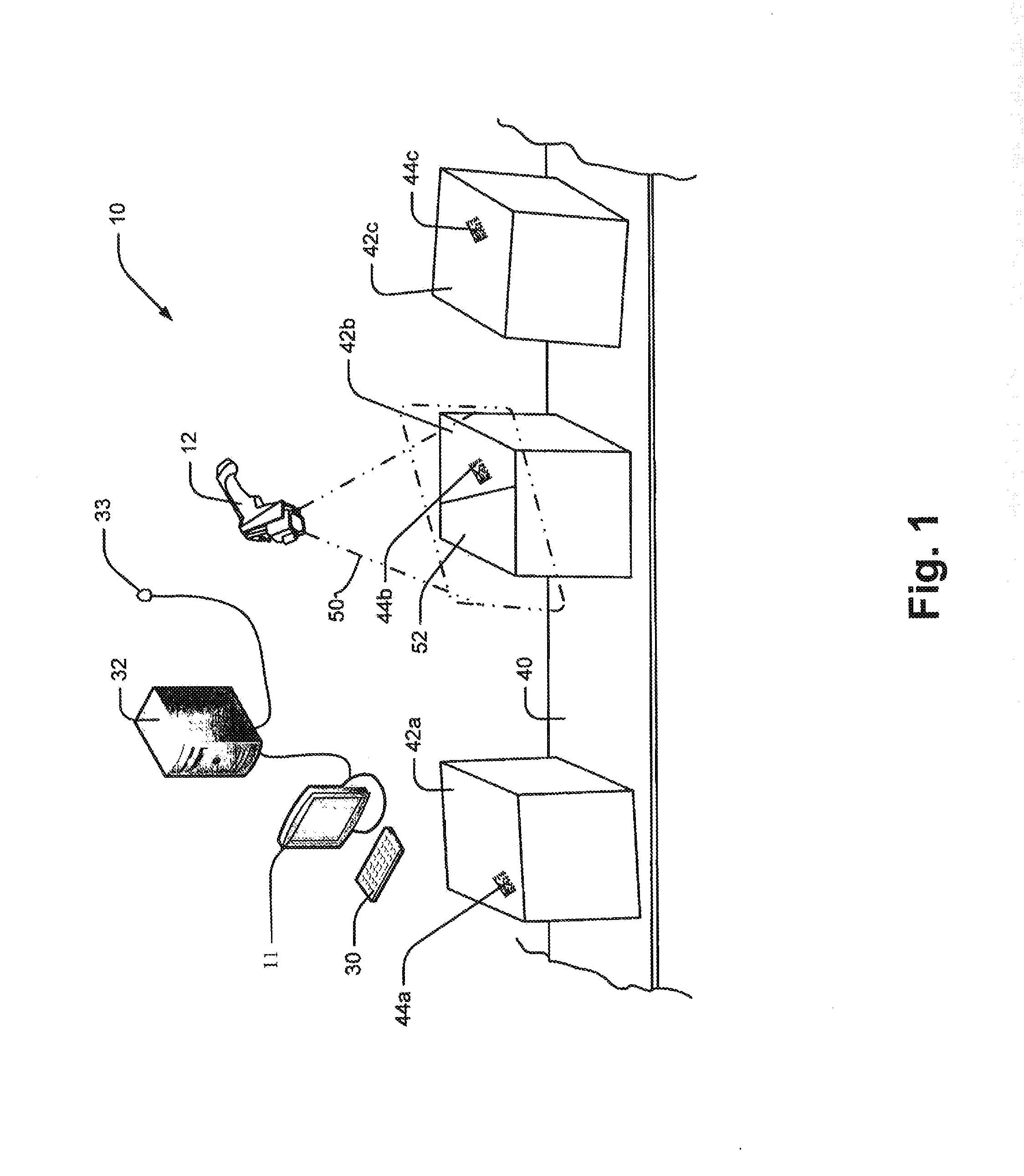
[0035]Referring now to the drawings wherein like reference numerals corresponding to similar elements throughout the several views and, more specifically referring to FIG. 1, the present invention will be described in the context of an exemplary materials handling assembly 10 that includes a transfer line 40 for moving cubic objects such as boxes or the like 42a, 42b, and 42c through a work station. Each of the objects is marked with a machine readable code (e.g., a bar code, a two-dimensional matrix code, etc.) where the codes are identified in FIG. 1 by numerals 44a, 44b and 44c that are applied to at least one of the surfaces of the object. In FIG. 1, code 44b is applied to exemplary surface 52 of object 42b. As objects 42a, 42b, 42c, etc., are moved to the station, equipment at the station is used to read the codes on the objects to identify the objects. In addition, station equipment is used to image objects and determine object dimensions. Where the objects needs to be loaded ...


PUM


Abstract

A handheld device and method using the device, the device comprising a sensor receiving light from within a field of view (FOV) to generate a plurality of consecutive images of the FOV, a structured light source that is controllable to generate a plurality of light patterns, the source arranged to project at least one light patterns into the FOV where at least a portion of a pattern reflects from an object and is captured by the sensor and a processor to receive images, the processor programmed to control the source to project a pattern into the FOV, locate the pattern in at least one of the generated images, locate discontinuities in the pattern and use the discontinuities to measure at least one dimension.

Description

CROSS-REFERENCE TO RELATED APPLICATIONS[0001]Not applicable.STATEMENT REGARDING FEDERALLY SPONSORED RESEARCH OR DEVELOPMENT[0002]Not applicable.BACKGROUND OF THE INVENTION[0003]This invention relates to handheld devices that project light patterns onto an object in a sensor field of view (FOV) having object features to be quantified, that obtain two dimensional images of the FOV including the patterns reflected off the object and that use the patterns in the images to quantify the object features.[0004]Handheld devices that project a light pattern onto an object in a sensor field of view (FOV) having a feature dimension to be measured, that obtain a two dimensional image of the FOV including the pattern reflected off the object and that use the pattern to identify the dimension to be measured are known. One problem with known devices of this type is that a device user is required to position the device such that the projected pattern is oriented in a specific fashion with respect to...

Claims


Application Information

Patent Timeline
IPC IPC(8): G01B11/00G06K7/10G06V10/141
CPCG01B11/25G06K7/10544G06T2207/10016G06T2207/10152G06T7/62G06V10/141G06V10/17G06V10/242G06V10/245G01B11/06G06K7/1417G06K2007/10524
Inventor MOED, MICHAEL C.GERST, III, CARL W.
Owner COGNEX CORP
Why Eureka
Try Eureka