Interface circuit

a technology of interface circuit and led array, which is applied in the use of semiconductor lamps, electroluminescent light sources, electric lighting sources, etc., can solve the problem of not being able to simply replace fluorescent lamps by led arrays, and achieve the effect of simple and effective way

Active Publication Date: 2014-01-23
KONINKLIJKE PHILIPS ELECTRONICS NV
View PDF2 Cites 8 Cited by
  • Summary
  • Abstract
  • Description
  • Claims
  • Application Information

AI Technical Summary

Benefits of technology

[0004]The invention aims to provide an interface circuit and a corresponding method that is capable of emulating a fluorescent lamp in a simple and effective way.

Problems solved by technology

Since LEDs and OLEDs need to be operated with a DC-current instead of a high frequency AC-current, it is not possible to simply replace the fluorescent lamp by a LED array.

Method used


Image

  • Interface circuit
  • Interface circuit
  • Interface circuit

Examples


Embodiment Construction

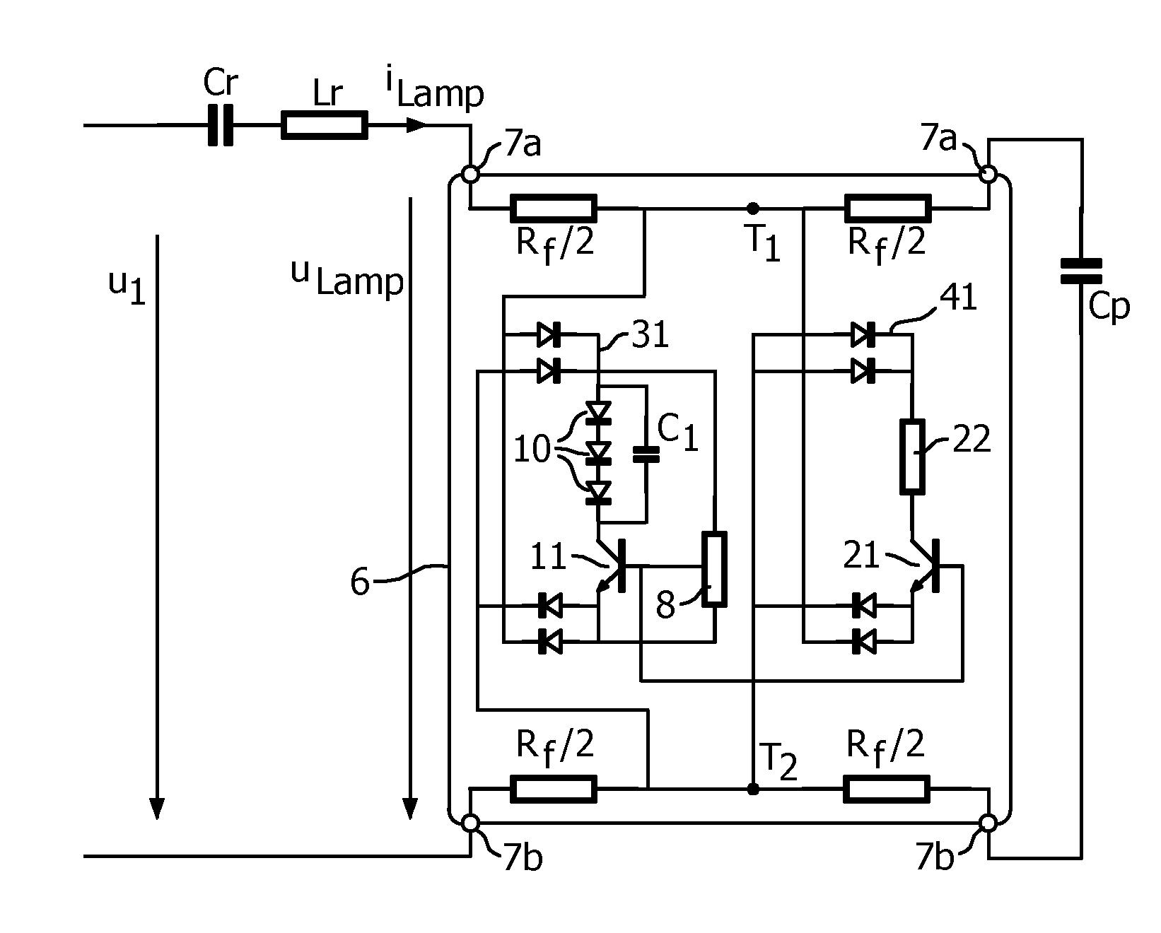
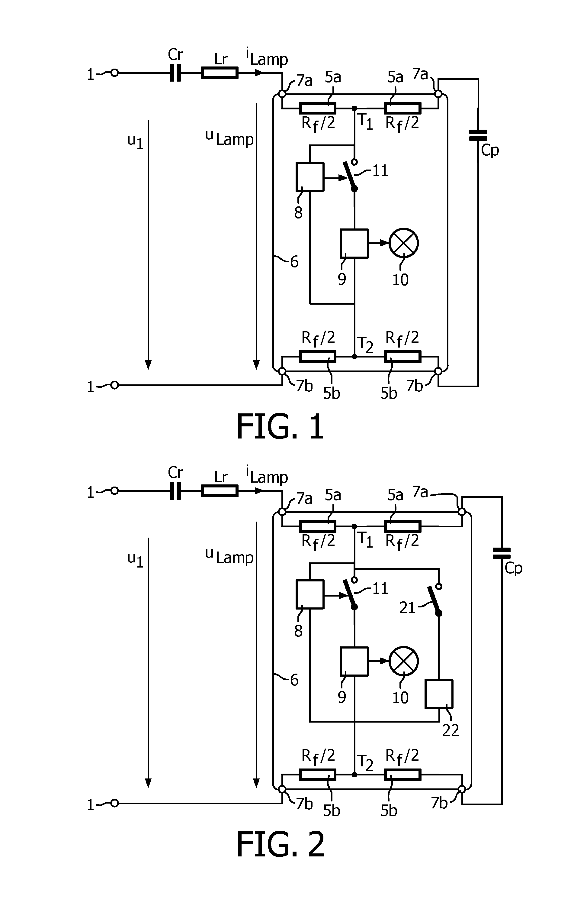
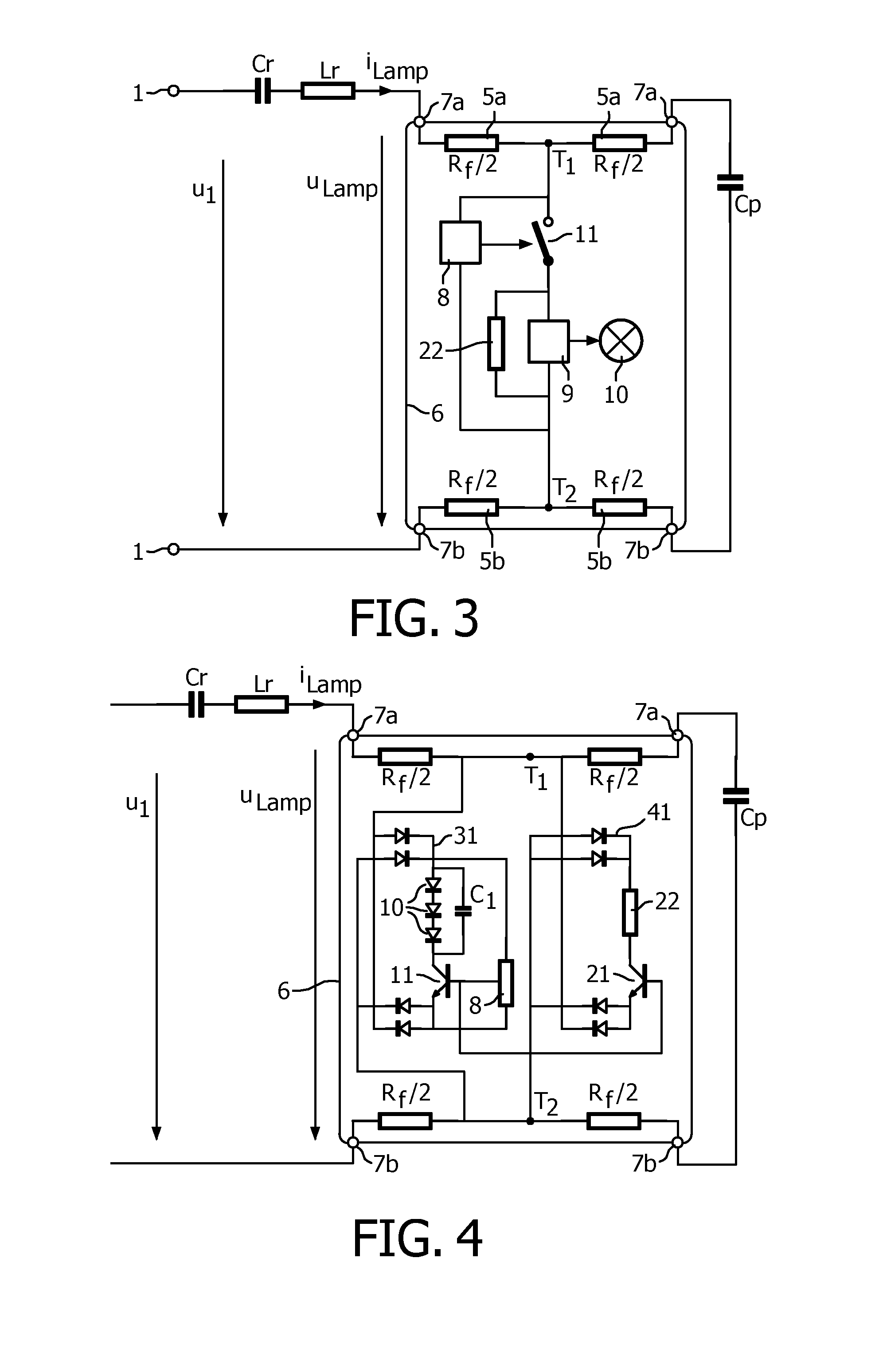
[0027]In FIG. 1, the terminals 1 are terminals comprised in a high frequency fluorescent lamp driver. Cr and Lr are a DC-blocking capacitor and a resonant choke, respectively, that are part of the high frequency fluorescent lamp driver. Reference numerals 7a and 7b are a first pair of input terminals and a second pair of input terminals, respectively, of the interface circuit, that are connected to lamp connection terminals of the high frequency fluorescent lamp driver. Reference numeral 5a is a first string interconnecting the first pair of input terminals 7a. Reference numeral 5b is a second string interconnecting the second pair of input terminals. Both strings comprise a series arrangement of two resistors, each having a resistance equal to half the resistance (Rf / 2) of a filament of a fluorescent lamp. It is remarked that the presence of the resistors in the first and second string is not absolutely necessary. Capacitor Cp connects an input terminal of the first pair to an inpu...


PUM


Abstract

An interface circuit is disclosed for operating a light source from an electronic fluorescent driver. In one example, the interface circuit comprises
    • input terminals for connection to lamp connection terminals of the electronic fluorescent lamp driver,
    • a first string interconnecting a first pair of input terminals,
    • a second string interconnecting a second pair of input terminals,
    • a third string interconnecting a first terminal of the first string and a second terminal of the second string and comprising a rectifier, output terminals of said rectifier being coupled during operation to the light source.
When a light source is operated making use of the interface circuit, a proper emulation of a fluorescent lamp is obtained.

Description

FIELD OF INVENTION[0001]The invention relates to an interface circuit for operating a light source by making use of a high frequency fluorescent lamp driver, and a corresponding method of operating a light source by making use of a high frequency fluorescent lamp driver.BACKGROUND OF THE INVENTION[0002]An interface circuit as mentioned in the opening paragraph is described in US2010 / 0033095 A1.[0003]Fluorescent lamps are highly efficient light sources that have been in use for many years. The efficiency and lifetime of fluorescent lamps are particularly high when they are driven by an electronic lamp driver that supplies a high frequency lamp current with a frequency in the order of 10 kHz. As a consequence, luminaires comprising such a high frequency fluorescent lamp driver are present in homes and offices all over the world. However, in recent years alternative electrically powered light sources in the form of LEDs and OLEDs or high pressure discharge lamps have become available t...

Claims


Application Information

Patent Timeline
Patent Type & Authority Applications(United States)
IPC IPC(8): H05B33/08H05B44/00
CPCH05B33/0818H05B33/0896H05B45/44Y02B20/30H05B45/39H05B45/3725H05B45/37H05B45/60
Inventor LOEF, CHRISTOPHTAO, HAIMIN
Owner KONINKLIJKE PHILIPS ELECTRONICS NV
Why Eureka
Try Eureka