
Fastener For Ornament With Pin

a technology of pins and fasteners, which is applied in the direction of fastening means, hats, medals, etc., can solve the problems of not being able to perform insertion and release operations smoothly, and not being able to exhibit reliable clamping, so as to improve the yield ratio, the effect of reliable retaining

Inactive Publication Date: 2014-01-23
KIKUNAGA ERI
View PDF19 Cites 2 Cited by
  • Summary
  • Abstract
  • Description
  • Claims
  • Application Information

AI Technical Summary

Benefits of technology

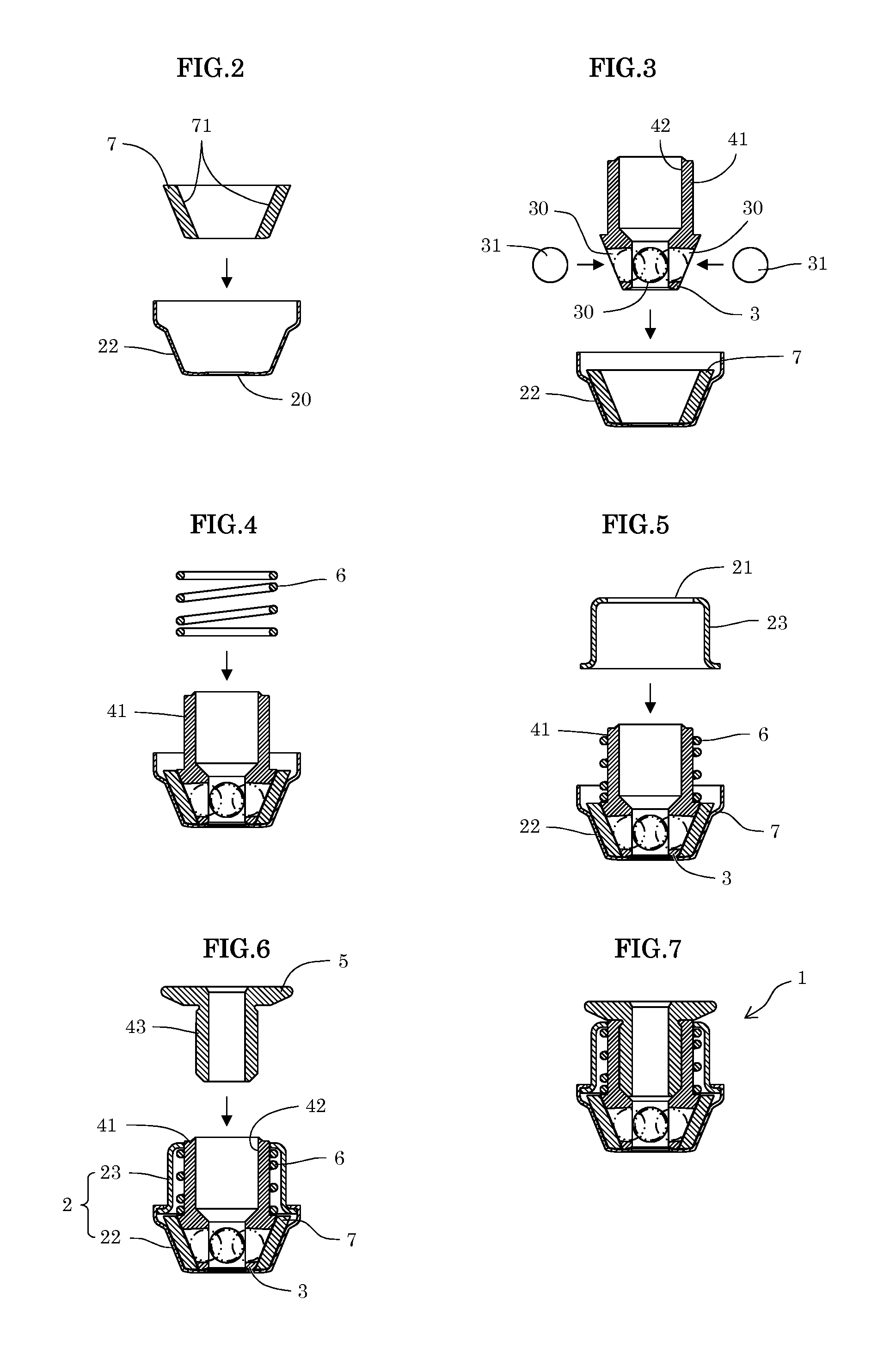
This patent describes a fastener for an ornament with a pin that can be attached to the ornament and retained securely, as well as being easily assembled and manufactured. The fastener includes an outer column portion integrated with a control lever, which can be inserted and attached only by being inserted into a clearance between the inner column portion with coil springs and the outer periphery of the inner column portion. This reduces the chance of assembly defects and maintains the yield ratio of the product. Additionally, the patent describes different methods for manufacturing the fastener, including pre-assembly of the components, covering the lower housing member with an upper housing member, and plating only the control lever and housing for cost reduction. Overall, the patent provides technical improvements in fastener design and manufacturing processes.

Problems solved by technology

However, with these prior arts, when, for example, the ornaments are pierced earrings, despite there being pins with pin diameters from 0.6 mm to 1.2 mm and thus differing by a factor of approximately 2, this is not accommodated adequately, and depending on the pressing force generated by the respective small balls, not only may it not be possible to exhibit reliable clamping forces in accordance with the types of pins that differ in diameter but it may also not be necessarily possible to perform an insertion operation and a release operation smoothly.

Method used


Image

  • Fastener For Ornament With Pin
  • Fastener For Ornament With Pin
  • Fastener For Ornament With Pin

Examples


Embodiment Construction

[0088]Then, attached drawings will be referred to describe the present invention on the basis of an embodiment.

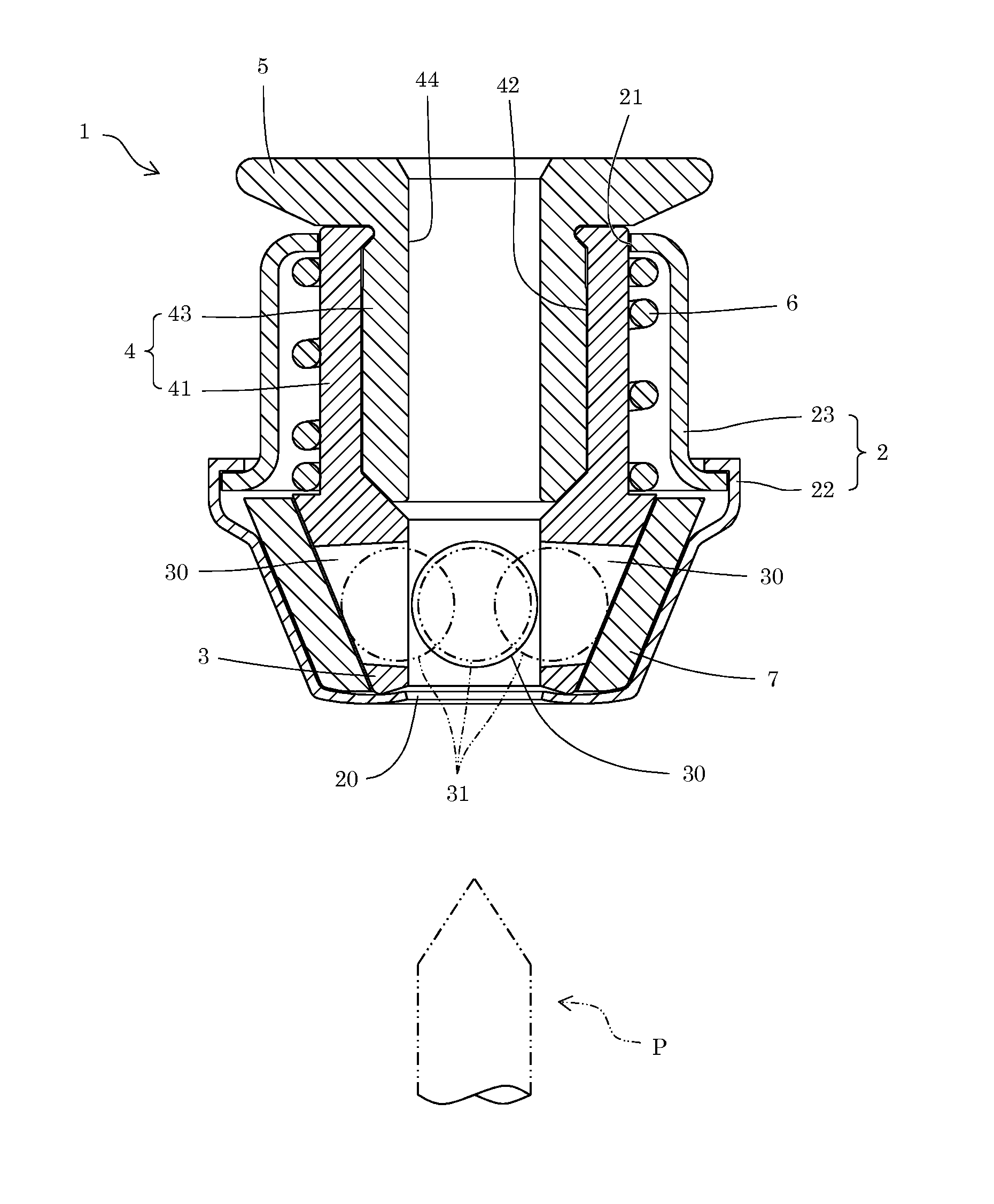
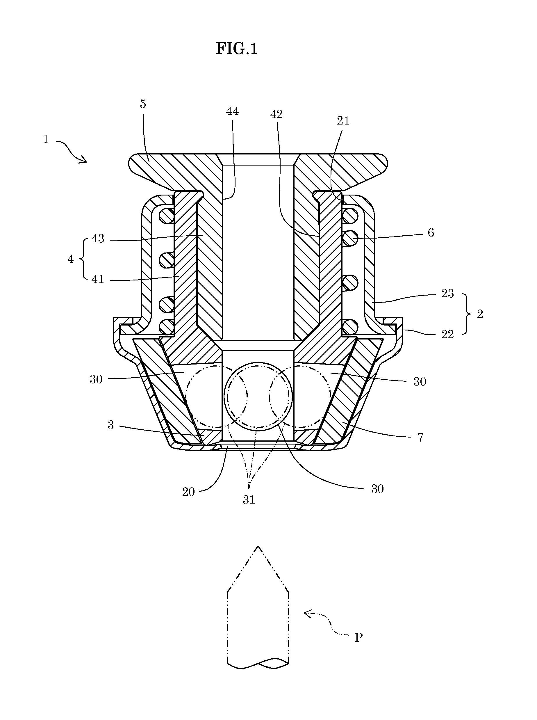
[0089]A fastener for an ornament having a pin described in the present invention (which may be, hereinafter, simply referred to as a fastener) is to retain the pin included in the ornament so as to be attached detachably. As shown in FIG. 1, a fastener 1 is constituted specifically with a housing 2 which has a pin passing hole 20 through which a pin P included in the ornament (not illustrated) is inserted and an opening portion 21 formed at a position directly opposite to the pin passing hole 20, a pin retaining portion 3 which is disposed inside the housing 2 to clamp and retain the pin P inserted through the pin passing hole 20 between the respective spherical surfaces of a plurality of small balls 31, 31, 31 (three balls in the present embodiment), a control lever 5 which is installed consecutively at the pin retaining portion 3 via a column portion 4 outside the opening...


PUM


Abstract

The present invention is to provide a fastener for an ornament having a pin which is excellent in workability on assembly and manufacture and improved in yield ratio, and the fastener of the present invention is characterized that the pin of the ornament is clamped in the fastener and retained between the respective spherical surfaces of a plurality of small balls, wherein a column portion inside a housing is provided with an outer column portion of a cylindrical body which is formed integrally with a pin retaining portion in a direction at which the pin retaining portion is pulled backward and internally has a through hole in the same direction as a direction at which the pin is inserted and an inner column portion of a cylindrical body which is inserted and fixed to the through hole inside the outer column portion, formed integrally with the control lever in a direction at which the control lever is urged and also has a through hole acting as a passage for introducing the pin inserted through the pin passing hole.

Description

BACKGROUND OF THE INVENTION[0001]1. Technical Field[0002]The present invention relates to a fastener for an ornament having a pin, more particularly, provides an art related to a fastener for an ornament having a pin which detachably retains the pin included in the ornament.[0003]2. Description of the Prior ArtBACKGROUND ART [0004]Examples of an ornament formed so that a pin included in the ornament can be retained detachably via a separately prepared fastener include pierced earrings, tiepins, buttons, etc., and as the fastener used in this case, those of various structures have been proposed from before.[0005]The fastener used here can largely be classified in terms of a basic structure into a type with which the pin is retained by an elastic body and a type with which the pin is retained by a plurality of small balls incorporated in the fastener.[0006]In regard to fasteners of the type with which the pin is retained by an elastic body, Patent Document 1 mentioned below discloses ...

Claims


Application Information

Patent Timeline
Patent Type & Authority Applications(United States)
IPC IPC(8): F16B21/00
CPCF16B21/00A44C7/003A44B9/08A44B1/34A44C3/001
Inventor KIKUNAGA, ERI
Owner KIKUNAGA ERI
Learn More