Closed loop drive circuit with external brake assist

a closed loop drive circuit and brake assist technology, applied in the direction of positive displacement liquid engine, piston pump, servomotor, etc., can solve the problems of frequent and rapid braking of the vehicle, and affecting the rotational speed

Active Publication Date: 2014-01-23
CATERPILLAR INC
View PDF1 Cites 12 Cited by
  • Summary
  • Abstract
  • Description
  • Claims
  • Application Information

AI Technical Summary

Benefits of technology

[0027]In one aspect the present disclosure is directed to a hydrostatic drive system for a vehicle. The hydrostatic drive system for a vehicle may comprise an open circuit, a closed circuit, and an electronic controller. The open circuit may include a main variable displacement hydraulic pump configured to be driven by an internal combustion engine equipped with a speed sensor. The main variable displacement hydraulic pump may be configured to supply hydraulic fluid to at least one hydraulic consumer via a hydraulic supply line. A pressure relief valve may be connected to a reservoir. The pressure relief valve may be permanently connected to the hydraulic supply line such that hydraulic fluid in the hydraulic supply line is discharged into the reservoir if a preset pressure level is reached in the open cir...

Problems solved by technology

Frequent and rapid braking of the vehicle is therefore necessary.
In particular, the wear of the conventional brakes is therefore relatively high.
This increase in the rotational speed is detrimental to the service life of the internal combustion engine and in addition leads to generally unacceptable high noise emissions.
Thus, the intended braking effect prevents the danger that the diesel engine will reach non-permissible high revolutions per unit time, which is particularly dangerous for diesel engines with turbochargers.
The problem described occurs in relation to the vehicle speed, its mass and the requisite brak...

Method used


Image

  • Closed loop drive circuit with external brake assist
  • Closed loop drive circuit with external brake assist
  • Closed loop drive circuit with external brake assist

Examples


Embodiment Construction

[0039]Reference will now be made in detail to the drawings. Wherever possible, the same reference numeral will be used throughout the drawings to refer to the same or like parts.

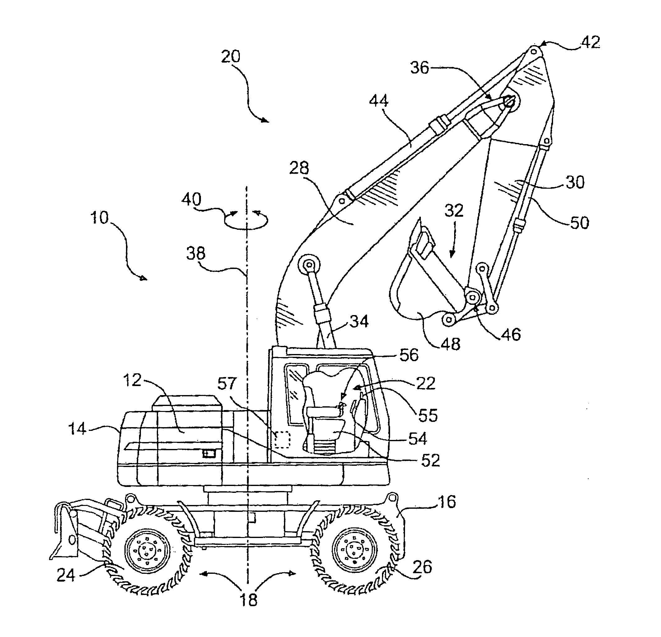
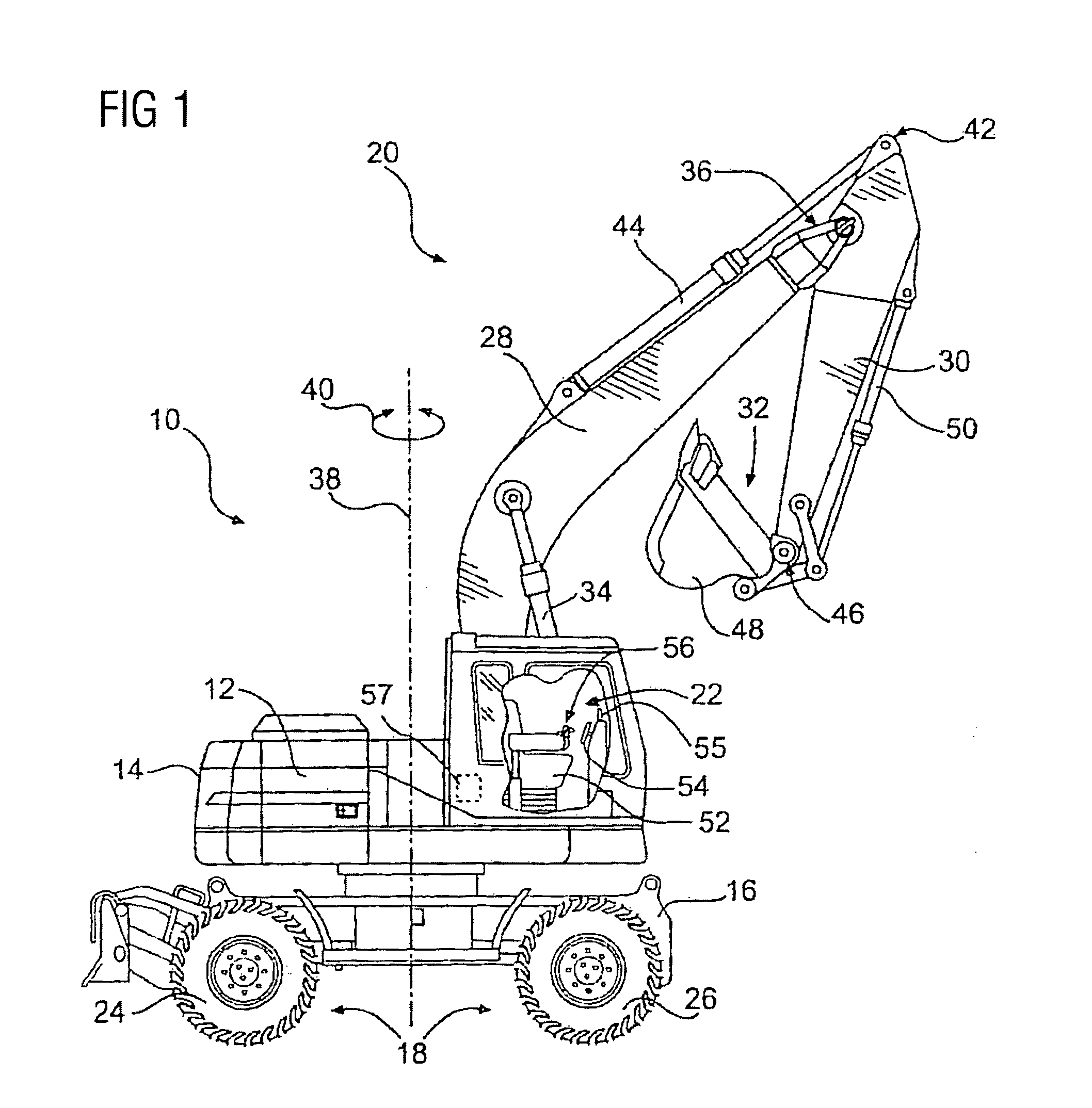
[0040]FIG. 1 shows a vehicle 10 as, e.g., a wheel excavator. Vehicle 10 may include a power source 12, and a frame 14, which may be operably attached to a base 16. Vehicle 10 may also include a traction system 18, e.g. a plurality of wheels 17, which may be operably attached to base 16. In addition, vehicle 10 may include a work implement 20 and an operator station 22 from which work implement 20 may be controlled.

[0041]Vehicle 10, although shown in FIG. 1 as a wheel excavator, may be any type of work machine with operator-controlled steering and travelling. For example, vehicle 10 may include wheel loaders, motor graders, backhoe loaders, skid steers, track-type tractors, tracked excavators, and any other type of work machine with operator-controlled steering and travelling.

[0042]Frame 14 may be fixedly mou...


PUM


Abstract

A hydrostatic drive system for a vehicle (10) comprises an open circuit (100), a closed travel circuit (120), an electronic controller (320), and a main variable displacement hydraulic pump (102) driven by an internal combustion engine (12) equipped with a speed sensor (350). The main variable displacement hydraulic pump may be configured to supply hydraulic fluid to a hydraulic consumer (34, 44, 50) via a hydraulic supply line (106). A pressure relief valve (118) may be connected to a reservoir (300) and may be permanently connected to the hydraulic supply line of the open circuit. The electronic controller may be configured to run a strong braking mode in which the electronic controller at least partially increases the displacement of the main variable displacement hydraulic pump such that hydraulic fluid is discharged via the permanently connected pressure relief valve into the reservoir if the sensed engine speed is higher than a predetermined maximum engine speed.

Description

TECHNICAL FIELD[0001]The present disclosure refers to a hydrostatic drive system for a vehicle, and particularly to a hydrostatic drive system comprising an open hydraulic circuit including a main hydraulic pump configured to be driven by an internal combustion engine and to drive at least one hydraulic consumer, and a closed hydraulic circuit including an auxiliary hydraulic pump configured to drive an hydraulic motor for travelling the vehicle.[0002]Furthermore, the present disclosure refers to a method for braking a vehicle, particularly a self-propelled construction machine such as, e.g., a wheel excavator.BACKGROUND[0003]Vehicles such as, e.g., self-propelled construction machines, having a hydrostatic drive are generally exposed to extreme fluctuations with regard to the load to be handled and with regard to the vehicle speed to be realized. Frequent and rapid braking of the vehicle is therefore necessary. In particular, the wear of the conventional brakes is therefore relativ...

Claims


Application Information

Patent Timeline
IPC IPC(8): F04B17/05
CPCF04B17/05B60T10/04B60T17/02E02F9/2235E02F9/2253E02F9/2289E02F9/2292E02F9/2296F15B11/17F16H61/4017F16H61/4148F16H61/4157F15B2211/20523F15B2211/20546F15B2211/20569F15B2211/20576F15B2211/251F15B2211/50536F15B2211/633F15B2211/6652F15B2211/6653F15B2211/7058F15B2211/7142F15B2211/85
Inventor BERG, TORSTEN
Owner CATERPILLAR INC
Why Eureka
Try Eureka