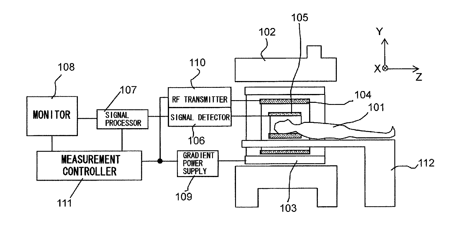
Magnetic resonance imaging device and magnetic resonance imaging method
a magnetic resonance imaging and magnetic resonance imaging technology, applied in the field of magnetic resonance imaging, can solve problems such as artifacts
- Summary
- Abstract
- Description
- Claims
- Application Information
AI Technical Summary
Benefits of technology
Problems solved by technology
Method used
Image
Examples
first embodiment
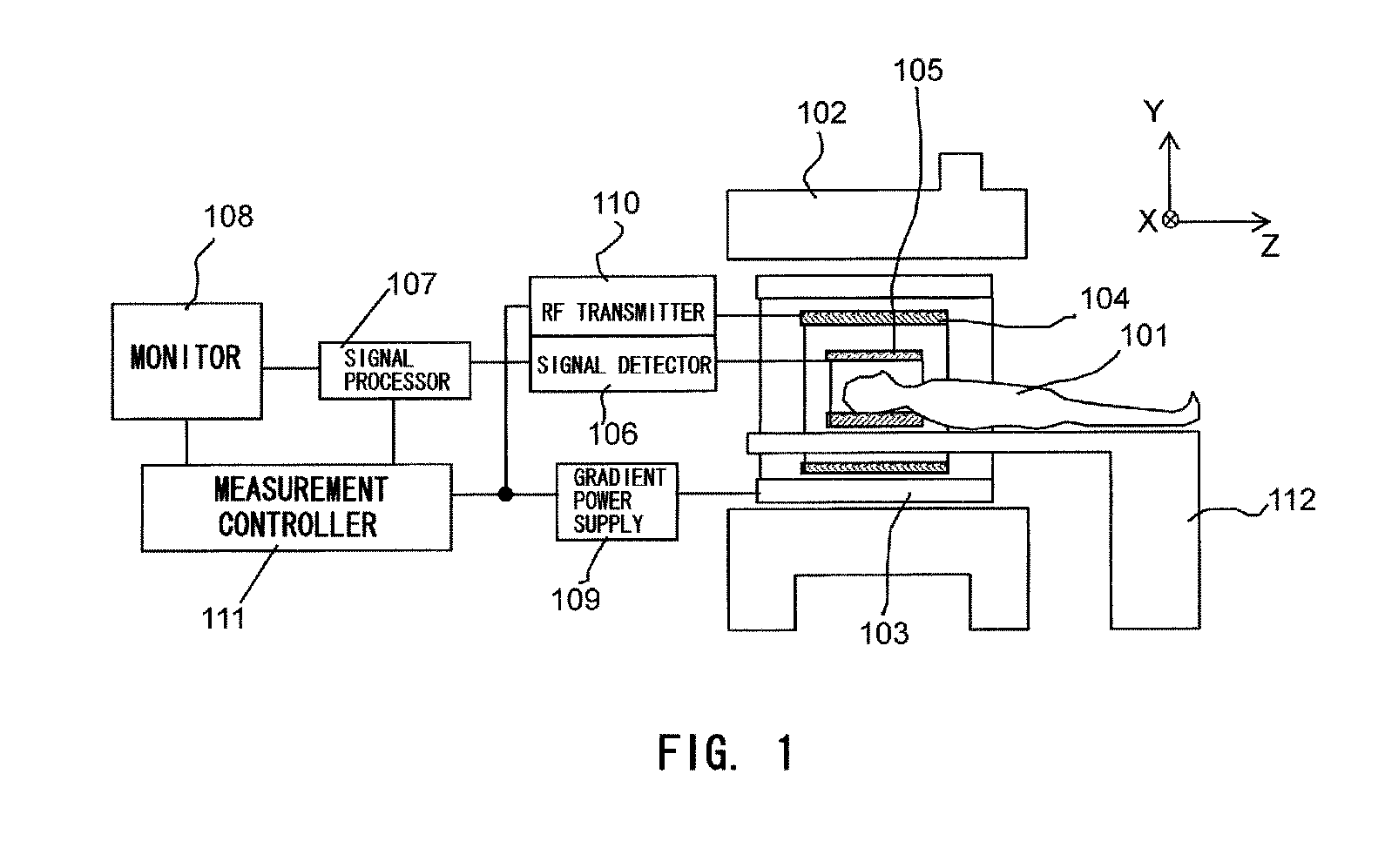
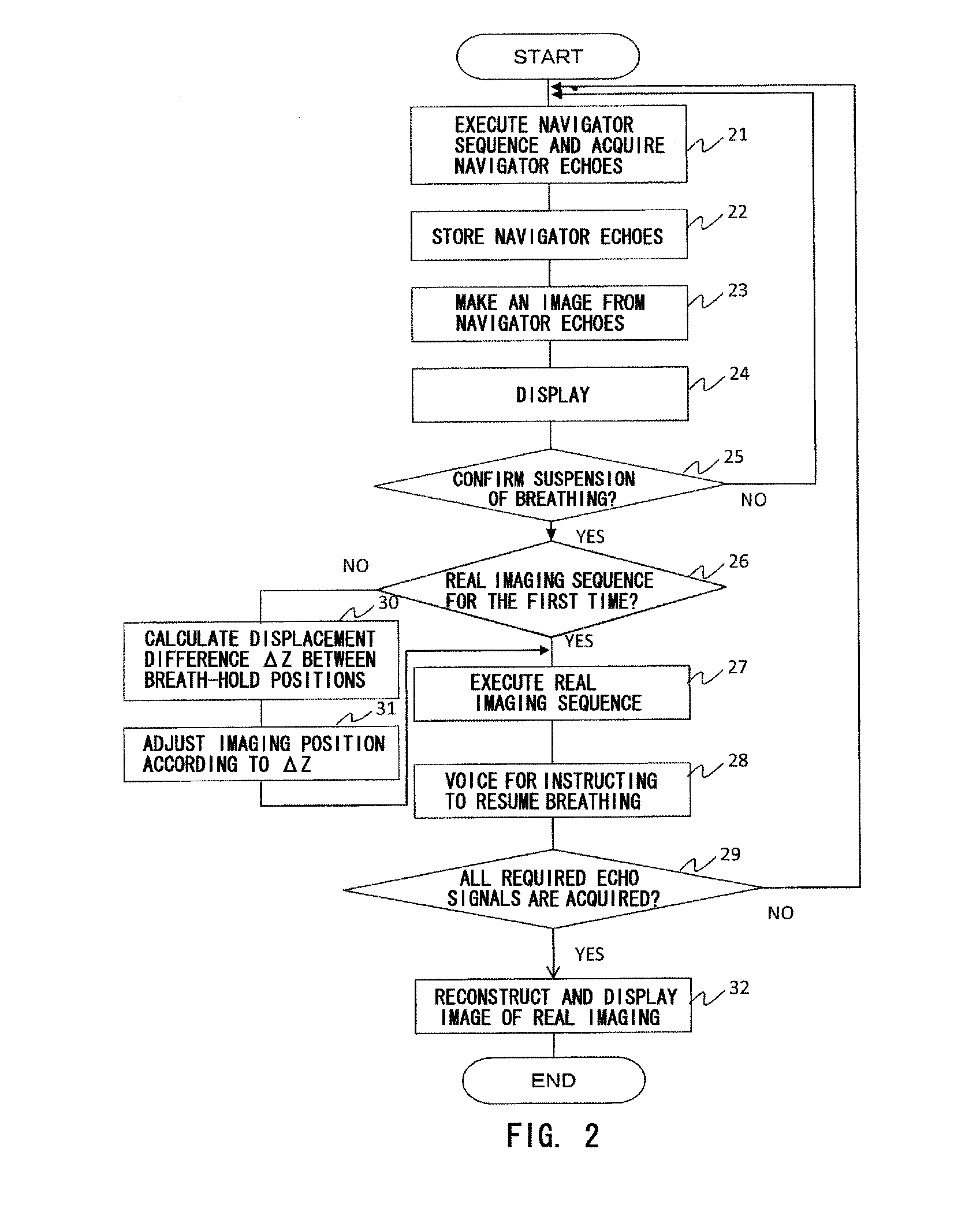
[0046]With reference to FIG. 2, FIG. 3, etc., an explanation will be made as to an operation of each part upon taking an image, in the first embodiment of the present invention. FIG. 2 is a flowchart illustrating an overall operation upon taking an image, and FIG. 3 illustrates a relationship among operations within the MRI device such as a navigator sequence and a real imaging sequence, respiratory displacement detected by navigator echoes, and manipulations by a user.
[0047]The measurement controller 111 reads and executes programs stored in the build-in memory, thereby controlling each part as shown in the flow of FIG. 2, and executing the imaging. Specifically, the measurement controller 111 controls each part, and executes the navigator sequence as shown in FIG. 4(a), thereby acquiring navigator echoes (step 21). According to this operation, respiratory movement of the subject is monitored. The position for acquiring the navigator echoes is optional, as far as it is a portion wh...
second embodiment
[0061]A second embodiment of the present invention will be explained. In the first embodiment, the real imaging sequence is started after the operator confirms that breath holding is actually performed, but there is a possibility that the breath-holding state may not be maintained until the end of the imaging. The second embodiment solves this problem.
[0062]FIG. 7 is a flowchart illustrating an overall operation of the imaging method according to the second embodiment. FIG. 8 illustrates a relationship among operations within the device such as the navigator sequence and the real imaging sequence, respiratory displacement detected by navigator echoes, and manipulations by the user. In those figures, the constitutional elements and processing being the same as those in the first embodiment are labeled the same.
[0063]Similar to the first embodiment, the navigator sequence 231 is executed repeatedly according to the steps 21 to 25, thereby acquiring navigator echoes continuously, and d...
third embodiment
[0071]The third embodiment will be explained. In the third embodiment, the measurement controller 111 uses the displacement amounts 707 and 708 in FIG. 10 to automatically determine the necessity of retaking in the real imaging sequence.
[0072]FIG. 11 is a flowchart illustrating the overall operation of the imaging method according to the third embodiment. FIG. 12 illustrates a relationship among operations within the device such as the navigator sequence and the real imaging sequence, respiratory displacement detected by navigator echoes, and manipulations by the user. In those figures, the configuration and processing being the same as those in the first and the second embodiment are labeled the same.
[0073]As shown in FIG. 11 and FIG. 12, resumption of breathing is instructed to the subject 101, after the first real imaging sequence 211 is finished and at the timing when a navigator echo is acquired in the initial sequence 201 of the second continuous navigator sequence 232 (steps ...
PUM
 Abstract
Description
Claims
Application Information
 - R&D
- Intellectual Property
- Life Sciences
- Materials
- Tech Scout
- Unparalleled Data Quality
- Higher Quality Content
- 60% Fewer Hallucinations
Browse by: Latest US Patents, China's latest patents, Technical Efficacy Thesaurus, Application Domain, Technology Topic, Popular Technical Reports.
© 2025 PatSnap. All rights reserved.Legal|Privacy policy|Modern Slavery Act Transparency Statement|Sitemap|About US| Contact US: help@patsnap.com


