
Apparatus for recognizing the discard state of a high-strength fiber rope in use in lifting gear

Active Publication Date: 2014-01-30
LIEBHERR COMPONENTS BIBERACH GMBH
View PDF13 Cites 25 Cited by
  • Summary
  • Abstract
  • Description
  • Claims
  • Application Information

AI Technical Summary

Benefits of technology

The present invention aims to provide an improved apparatus for accurately determining the discard state of high-strength fiber ropes. The apparatus should be reliable, precise, and cost-effective, while managing to utilize the remaining service life of the fiber rope without compromising safety and reliably operating under difficult conditions of use for construction machinery.

Problems solved by technology

A disadvantageous property of such high-strength fiber ropes is, however, their break behavior or their failure without substantial, longer preliminary signs.
Such monitoring measures of the hoist winch can, however, not really reliably give the remaining service life or the discard state of a high-strength fiber rope since the high-strength fiber ropes are subject to a variety of strains and impairments which influence the wear and which are independent of the winch strain, for instance e.g. the deflection and bending strains at pulley blocks, external blows and buffets on the rope, surface contamination of components contacting the rope, etc.
On the other hand, inflexible service life standards for high-strength fiber ropes are practically incompatible with respect to economic utilization of the actual service life and observation of the required safety since the service life and wear of the high-strength fiber rope can fluctuate strongly in dependence on the conditions of use and on the external influences on the high-strength fiber rope.

Method used


Image

  • Apparatus for recognizing the discard state of a high-strength fiber rope in use in lifting gear
  • Apparatus for recognizing the discard state of a high-strength fiber rope in use in lifting gear
  • Apparatus for recognizing the discard state of a high-strength fiber rope in use in lifting gear

Examples


Embodiment Construction

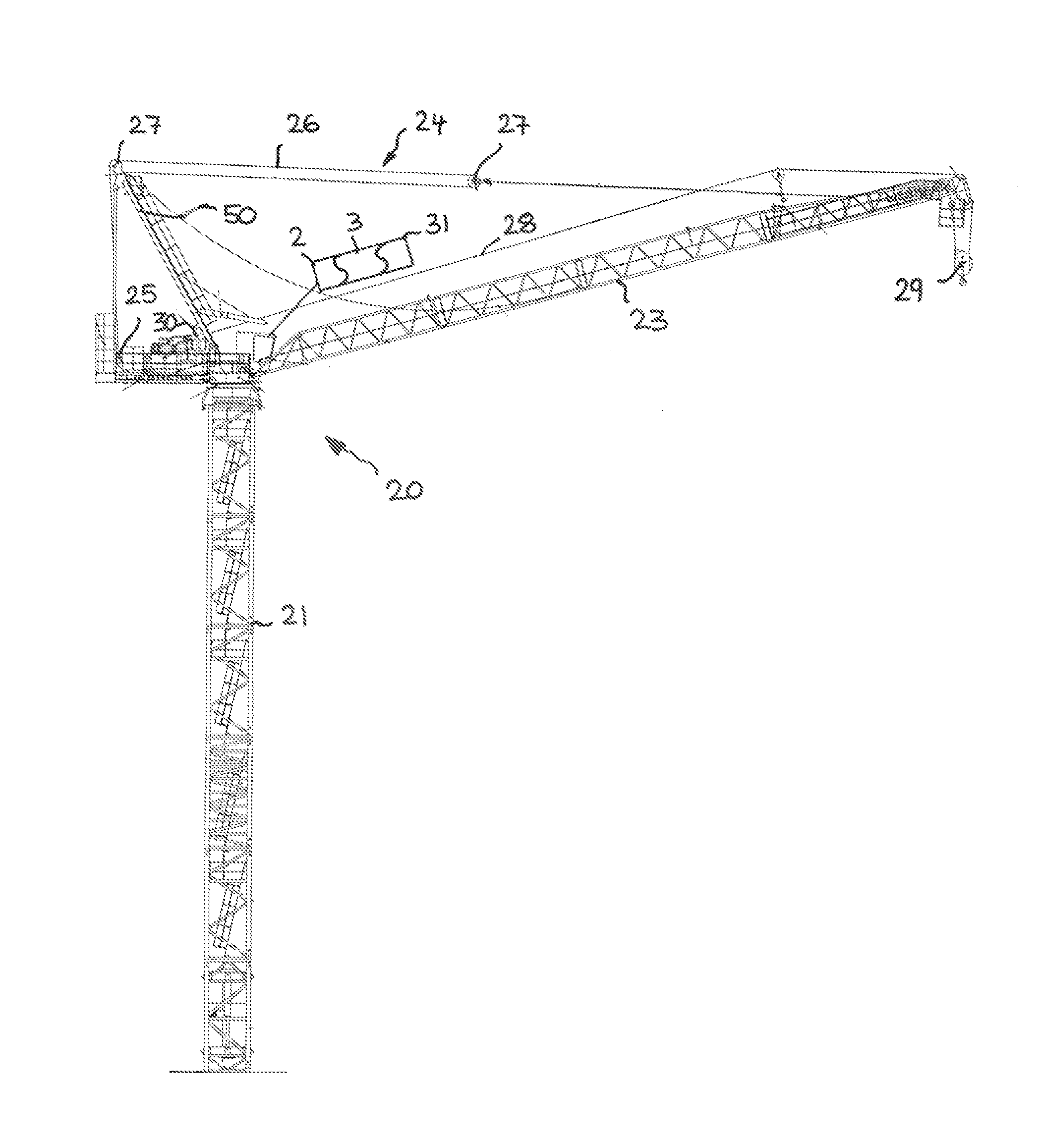
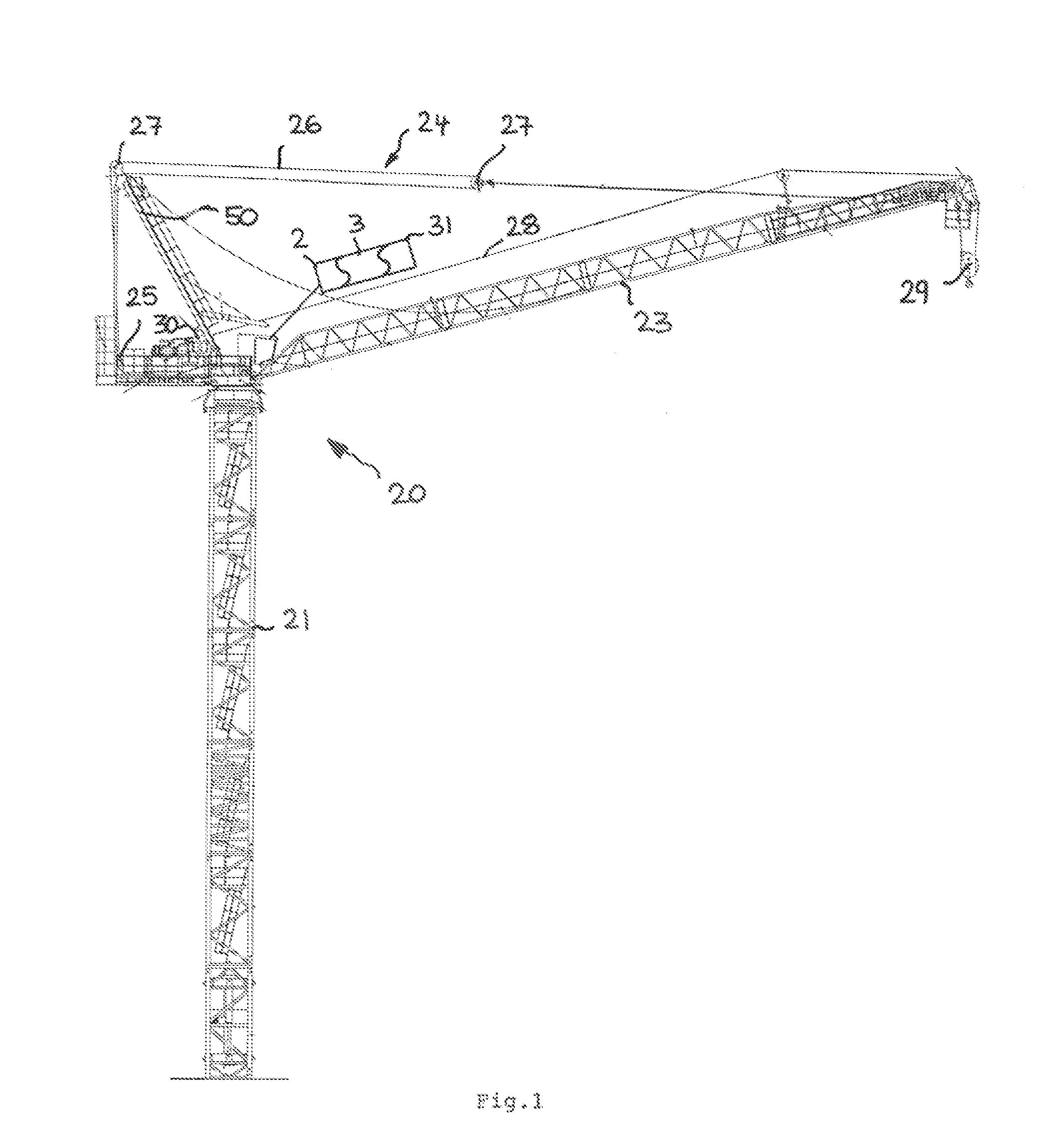
[0045]FIG. 1 shows by way of example for lifting gear in accordance with an advantageous embodiment of the invention a crane in the form of as revolving tower crane 20 which revolves at the top and whose tower 21 is supported on a carriage or on a stationary base. A boom 23 is pivotably connected to the tower 21 in a luffable manner about a horizontal axis in a manner known per se and is guyed via a guying rope arrangement 24. The named guying rope arrangement 24 can be varied in its length via a guying rope winch 25 so that the working angle of the boom 23 can be changed. For this purpose, a guy rope 26 runs onto the named guy rope winch 25. The guy rope 26 or the guying rope arrangement 24 is guided at a pivot point at the boom 23 close to the tip of the boom 23 via, for example, pulley blocks 27 at the shown guy brace 50 or a tower tip.

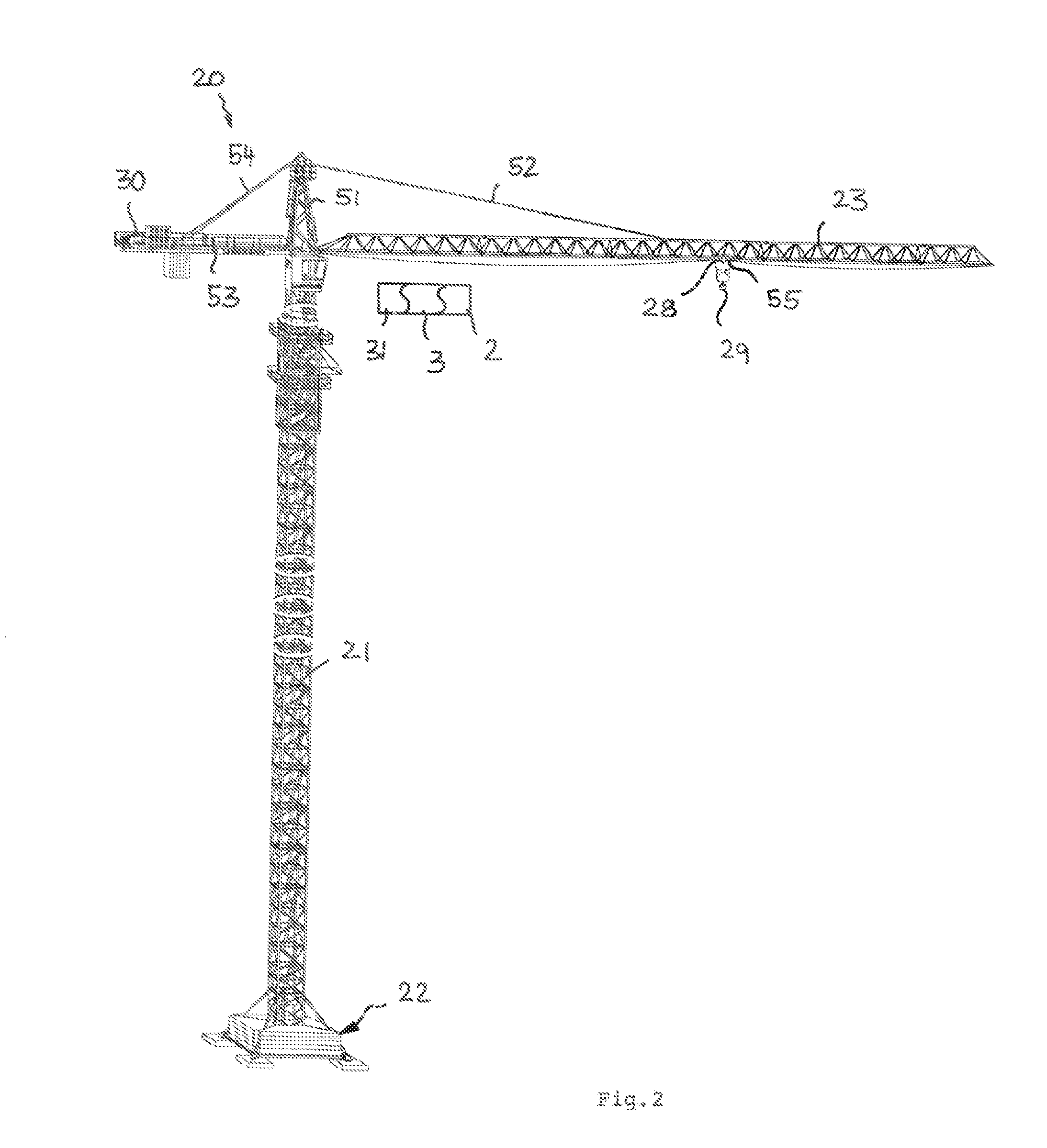
[0046]As FIG. 2 shows, the revolving tower crane 20 can naturally also be provided with a trolley boom. The revolving tower crane 20 which likewis...


PUM


Abstract

The present invention relates generally to lifting gear such as cranes which use high-strength fiber ropes instead of steel ropes. In this respect, the invention in particular relates to an apparatus for recognizing the discard state of a high-strength fiber rope in use at such lifting gear comprising a detection device for detecting at least one rope parameter as well as comprising an evaluation unit for evaluating the rope parameter and for providing a discard signal in dependence on the rope parameter evaluation. In accordance with the invention, the detection device of the apparatus for recognizing the discard state comprises a plurality of differently configured detection means for a magnetic, mechanical, optical and / or electronic detection of a plurality of different rope parameters which can be evaluated by the evaluation unit individually and / or in combination with one another for recognizing the discard state.

Description

CROSS-REFERENCE TO RELATED APPLICATIONS[0001]This application is a continuation of PCT Application No. PCT / EP2012 / 000311, filed 24 Jan. 2012, which claims priority to German Patent Application No. 20 2011 001 846.6, filed 24 Jan. 2011, both of which are incorporated herein in their entireties.BACKGROUND[0002]1. Technical Field[0003]The present invention relates generally to lifting gear such as cranes which use high-strength fiber ropes instead of steel ropes. In this respect, the invention in particular relates to an apparatus for recognizing the discard state of a high-strength fiber rope in use at such lifting gear comprising a detection device for detecting at least one rope parameter as well as comprising an evaluation unit for evaluating the rope parameter and for providing a discard signal in dependence on the rope parameter evaluation.[0004]2. Description of Related Art[0005]In recent times, trials have been made with cranes to use high-strength fiber ropes made from synthet...

Claims


Application Information

Patent Timeline
IPC IPC(8): G01N33/36B66C15/06G01N3/08
CPCG01N33/36B66C15/06G01N3/08B66C13/16B66C15/00B66D1/54B66C13/18G01N3/14
Inventor ILAKA, MUPENDEZERZA, HORST
Owner LIEBHERR COMPONENTS BIBERACH GMBH
Learn More