Power converter for engine generator

Active Publication Date: 2014-01-30
ILLINOIS TOOL WORKS INC
View PDF43 Cites 60 Cited by
  • Summary
  • Abstract
  • Description
  • Claims
  • Application Information

AI Technical Summary

Problems solved by technology

In systems designed for power conversion, particular challenges exist

Method used


Image

  • Power converter for engine generator
  • Power converter for engine generator
  • Power converter for engine generator

Examples


Embodiment Construction

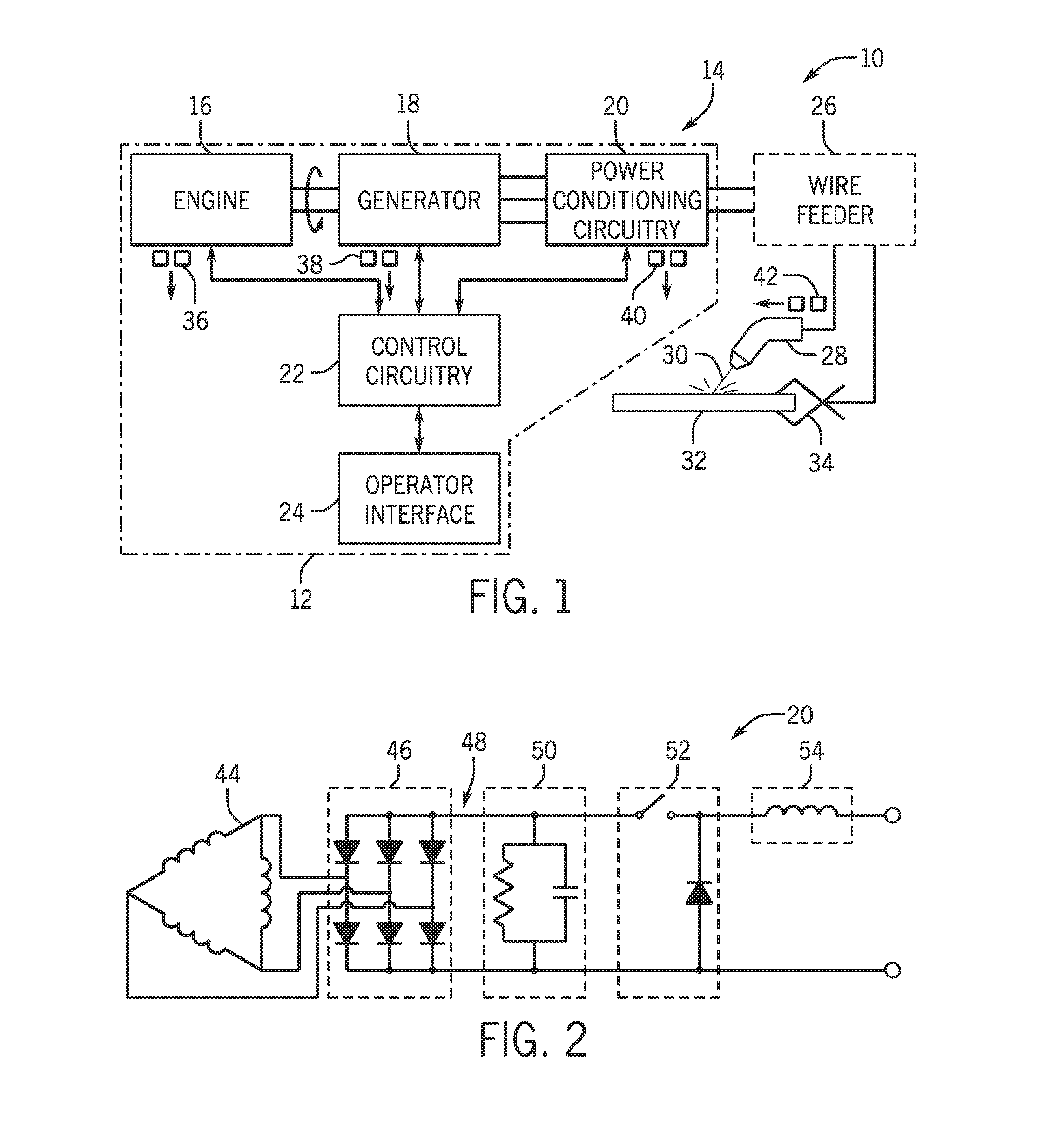
[0018]Turning now to the drawings, and referring first to FIG. 1, an exemplary welding system 10 is illustrated that includes a power supply 12 for providing power for welding, plasma cutting and similar applications. The power supply 12 in the illustrated embodiment comprises an engine generator set 14 that itself includes an internal combustion engine 16 and a generator 18. The engine 16 may be of any suitable type, such as gasoline engines or diesel engines, and will generally be of a size appropriate for the power output anticipated for the application. The engine will be particularly sized to drive the generator 18 to produce one or more forms of output power. In the contemplated application, the generator 18 is wound for producing multiple types of output power, such as welding power, as well as auxiliary power for lights, power tools, and so forth, and these may take the form of both AC and DC outputs. Various support components and systems of the engine and generator are not...


PUM


Abstract

A power converter for an engine generator includes an insulative support that receives and supports circuit components for converting incoming AC power to desired power, such as power suitable for a welding application. One or more rectifier modules are provided that are received and supported by the support. Three such modules may be provided for receiving three phase power from a generator. DC power from the rectifier module is applied to DC bus plates. The plates may be coupled to capacitors. A power conversion circuit, such as a buck converter, is coupled to the DC bus plates to convert the DC power to output power.

Description

CROSS REFERENCE TO RELATED APPLICATIONS[0001]This application is a Non provisional U.S. patent application of U.S. Provisional Application No. 61 / 676,769, entitled “Power Converter for Engine Generator”, filed Jul. 27, 2012, which is hereby incorporated by reference in its entirety.BACKGROUND[0002]The present invention relates generally to the field of power conversion, and particularly to power conversion circuits used in power electronic equipment such as welding systems, plasma cutters, and so forth.[0003]Many power electronic machines used in industry employ circuitry for converting power from one useful form to another. For example, welding and plasma cutting systems generally receive alternating current (AC) power from a source, such as the power grid or an engine generator. The power is typically converted to direct current (DC) power via rectifiers, then distributed on a DC bus to further power conversion circuitry. This further power conversion circuitry may include inverte...

Claims


Application Information

Patent Timeline
IPC IPC(8): H02M7/00H02K7/18G05F1/02H02M1/00
CPCH02M7/003H02K7/1815G05F1/02B23K9/10B23K9/32H02M1/34H02M3/157H02M7/00H05K7/14H05K7/20H02M1/42H05K7/209H05K7/14322H05K7/1432H02M1/007H02M7/2173H02P9/00
Inventor JOCHMAN, NATHAN J.
Owner ILLINOIS TOOL WORKS INC
Why Eureka
Try Eureka