Low Supply Voltage Logic Circuit
- Summary
- Abstract
- Description
- Claims
- Application Information
AI Technical Summary
Benefits of technology
Problems solved by technology
Method used
Image

Examples
Embodiment Construction
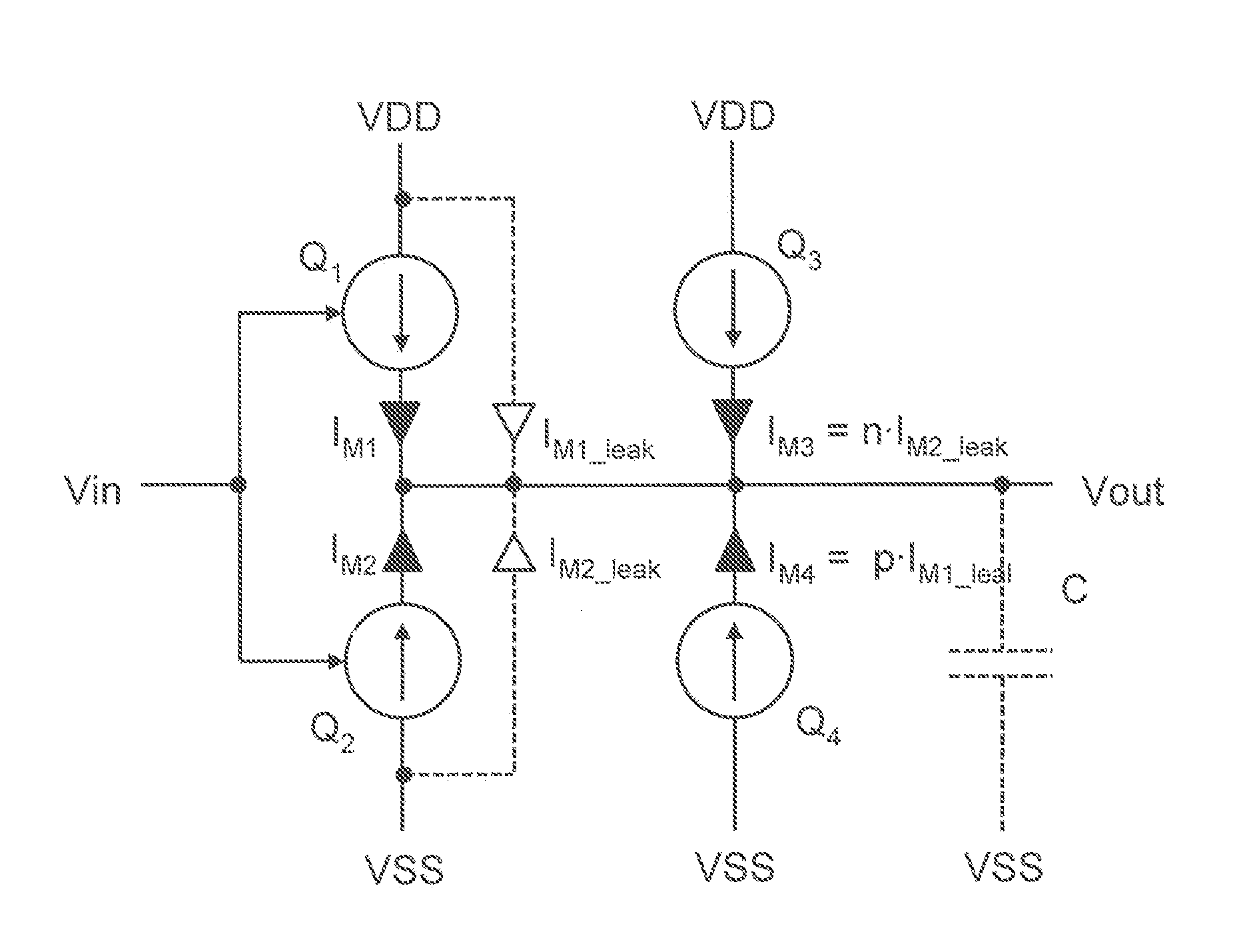
[0012]An improved sub-threshold logic circuit, which may be, for instance, an inverter as shown in the circuit diagram of FIG. 1, forms a basic low-voltage digital logic cell which can be adapted in different ways to create all other types of logic cells such as gates (e.g., AND, NAND, OR, NOR, XAND, XOR gates), oscillators (e.g., ring oscillators, RC feedback oscillators), delays (runtime delays, RC delays), comparators and the like. The sub-threshold inverter of FIG. 1 includes two controllable current sources, first current source Q1 and second current source Q2, which form a common inverter circuit. Current source Q1 has a first controlled current path which is connected between a first supply line for an, e.g., positive, supply potential VDD and an output line for an output signal Vout of the inverter. The output signal Vout drives a load, e.g., a capacitance C which may be established by the capacitance of the output line. Current source Q2 has a second controlled current path...
PUM
 Abstract
Description
Claims
Application Information
PatSnap Eureka turns technology decisions into work you can execute. Powered by our Innovation Knowledge Graph, it runs expert workflows across engineering, life sciences, materials and intellectual property. Get your review-ready output in minutes.


