X-ray generating apparatus for paracentesis

a technology of generating apparatus and paracentesis, which is applied in the direction of electrical apparatus, x-ray tube vessel/container, electric discharge tube, etc., can solve the problems of difficult to effectively and efficiently treat the affected part, and the conventional x-ray generating apparatus cannot adjust a region

Inactive Publication Date: 2014-01-30
CANON KK
View PDF5 Cites 9 Cited by
  • Summary
  • Abstract
  • Description
  • Claims
  • Application Information

AI Technical Summary

Problems solved by technology

However, conventional X-ray generating apparatuses for paracentesis cannot adjust a region to be irradiated with X-ray, so as to match the size and the position of the affected part (cannot adjust size or position of region which X-ray

Method used


Image

  • X-ray generating apparatus for paracentesis
  • X-ray generating apparatus for paracentesis
  • X-ray generating apparatus for paracentesis

Examples


example 1

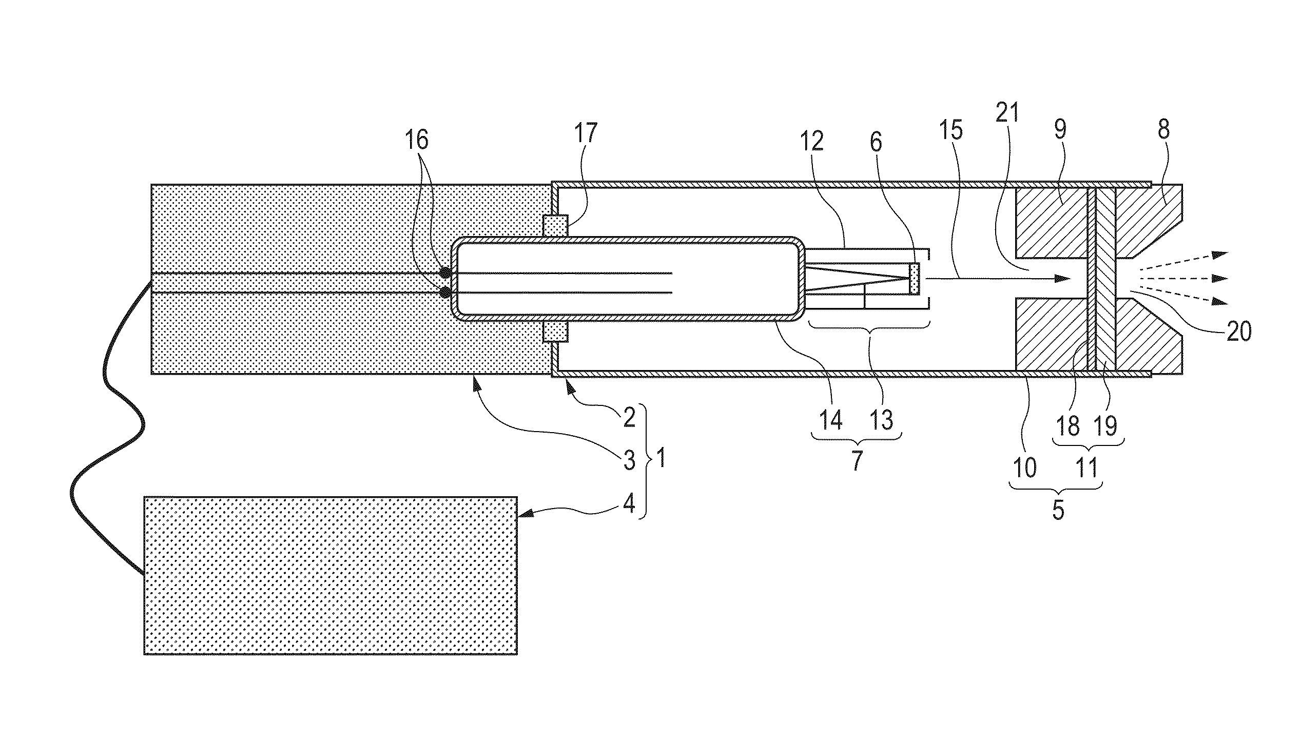
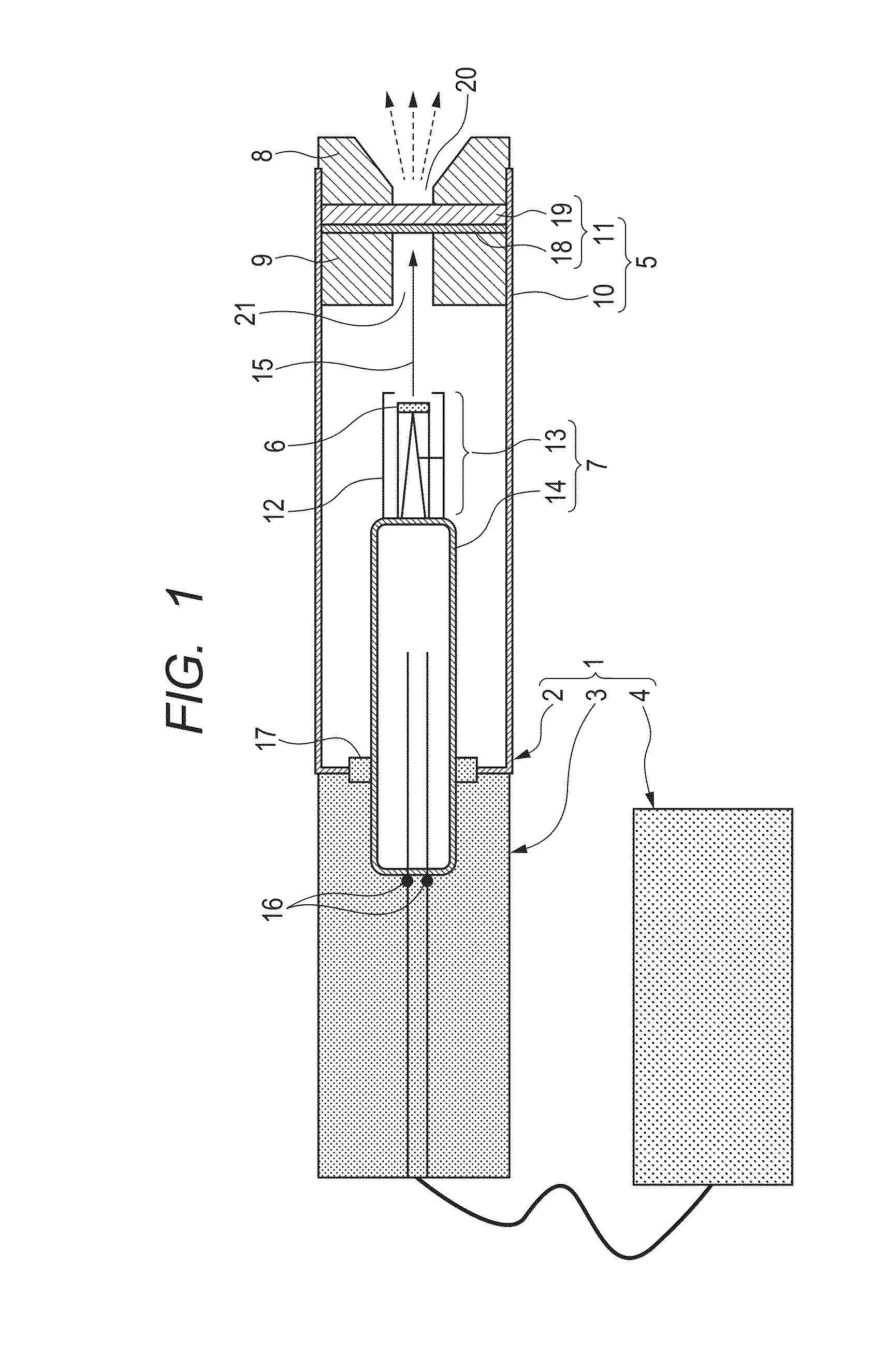
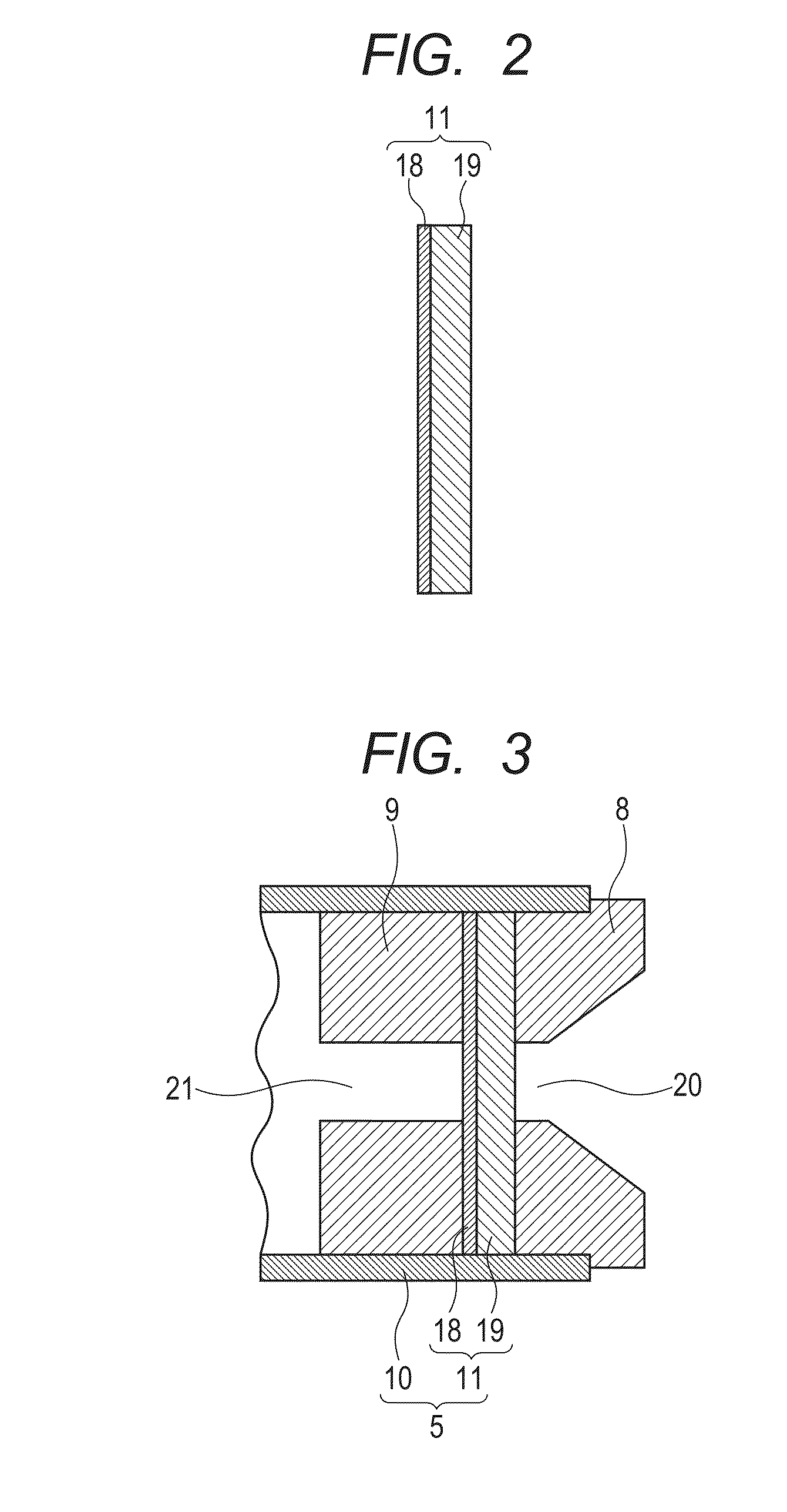
[0044]An X-ray generating apparatus 1 for paracentesis was manufactured, which was illustrated in FIG. 1 to FIG. 3.

[0045]Specifically, firstly, a diamond substrate was prepared as a substrate 19, which was produced by high-pressure synthesis made by Sumitomo Electric Industries, Ltd. The substrate has a discal shape (cylindrical shape) having a diameter of 5 mm and a thickness of 1 mm, and has a thermal conductivity of 2,000 W / m / K at room temperature. An organic substance depositing on the surface of the substrate was removed beforehand by a UV-ozone asher.

[0046]A target layer 18 made from tungsten was formed on one face of this substrate 19 by sputtering with the use of Ar as a carrier gas, so as to have a thickness of 7 μm. When the tungsten film was formed, the substrate 19 was heated to 260° C. on a stage. The thermal conductivity of each layer was evaluated by a monitor substrate which was previously prepared in a film-forming process, and as a result, the thermal conductivity ...

example 2

[0054]A mechanism in which an insulating oil transferred heat was provided so as to come into contact with an envelope 5 illustrated in FIG. 1. The structures of the envelope 5 and the inner part thereof are similar to those in Example 1. A mechanism was also provided so as to inject and discharge the insulating oil for cooling from the middle of a grip portion 3 through an unillustrated temperature control device. The grip portion 3 was structured so that the coaxial internal conductor was covered with a stacked body of a reticulated flexible silicon resin, and a mechanism was provided in which the insulating oil circulated in the mesh of the reticulated flexible silicon resin. Thereby a temperature rise could be controlled which occurred when the X-ray were emitted.

[0055]The insulating oil was brought into contact with an introduction terminal 16, the rear portion of a flange portion 14, and the rear end portion of the envelope 5 and circulated between the portions and the tempera...

example 3

[0056]The X-ray generating apparatus for paracentesis was structured similarly to that in Example 1, except that an electrode 22 was further added to the outside of a control electrode 12 in an accelerating portion 13, as illustrated in FIG. 7. The potential of the control electrode 12 was appropriately controlled, and thereby the diameter of an electron beam 15 which was converged on the target layer 18 could be controlled to 1 mm or smaller. In addition, an X-ray sensor was provided in the outside of the body, and thereby the arrangement of the periphery of the affected part which was irradiated with the X-ray in the body could be accurately detected through a transmission image.


PUM


Abstract

An X-ray generating apparatus for paracentesis of the present invention has an electron emitting portion arranged in an envelope, and a target that emits X-ray by irradiation with electrons that are emitted from the electron emitting portion, and irradiates an affected part in a living body with the X-ray which have been emitted from the target. The apparatus can adjust a region to be irradiated with X-ray, and thereby enables the affected part to be more effectively and efficiently treated with X-ray.
The apparatus also includes a front shield which is provided so as to protrude to the outside from the envelope and has an opening that forms a passage of the X-ray which irradiate the affected part, and can adjust a region to be irradiated with X-ray which irradiate the affected part, by the exchange of the front shield.

Description

BACKGROUND OF THE INVENTION[0001]1. Field of the Invention[0002]The present invention relates to an X-ray generating apparatus for paracentesis, which is used in a medical field or an industrial field.[0003]2. Description of the Related Art[0004]An X-ray generating apparatus is known for paracentesis to treat an affected part by irradiation with X-ray. Japanese Patent No. 3,090,910 discloses a reflection type of X-ray generating apparatus which mounts a cold cathode that is an electron emitting portion and a target provided in a thin envelope, and is configured so that an electric power for driving can be supplied through a coaxial cable which is connected to the rear end of the envelope. When the electric power is supplied, the cold cathode emits electrons, the electrons irradiate the target to generate X-ray, and the X-ray irradiates the affected part through a window portion which is provided on a lateral side of the head side of the envelope.[0005]In addition, U.S. Pat. No. 7,38...

Claims


Application Information

Patent Timeline
IPC IPC(8): H01J35/16
CPCH01J35/16H01J35/32H01J2235/166H01J35/116H01J35/186
Inventor ONO, TAKEO
Owner CANON KK
Why Eureka
Try Eureka