Stress-measuring device and method

a stress-measuring device and stress-measuring technology, applied in the field of stress-measuring devices and methods, can solve the problems of more bodily processes to change, long-term stress, etc., and achieve the effect of less obtrusiveness and less expensiv

Active Publication Date: 2014-01-30
KONINKLIJKE PHILIPS ELECTRONICS NV
View PDF10 Cites 10 Cited by
  • Summary
  • Abstract
  • Description
  • Claims
  • Application Information

AI Technical Summary

Benefits of technology

[0007]It is an object of the present invention to provide a (long-term) stress-measuring device and method for determining a level of stress of a user, in particular long-term stress, which provides a context situation independent detection of the stress level. It is also an objective of the present invention to provide such a stress-measuring device and method which is less obtrusive and / or less expensive. Further, it is an object of the present invention to provide a wearable device comprising such stress-measuring device, a stress-measuring system, comprising such stress-measuring device and a computer program implementing such stress-measuring method.

Problems solved by technology

Long-term stress occurs when short-term stress happens too often, without sufficient possibility to recover from it.
The effects build up, causing more bodily processes to change or be disturbed, resulting possibly in illnesses because of a weaker immune system, burn-out syndrome and the like.
The general problem with physiological signals is a good interpretation of these signals.

Method used


Image

  • Stress-measuring device and method
  • Stress-measuring device and method
  • Stress-measuring device and method

Examples


Embodiment Construction

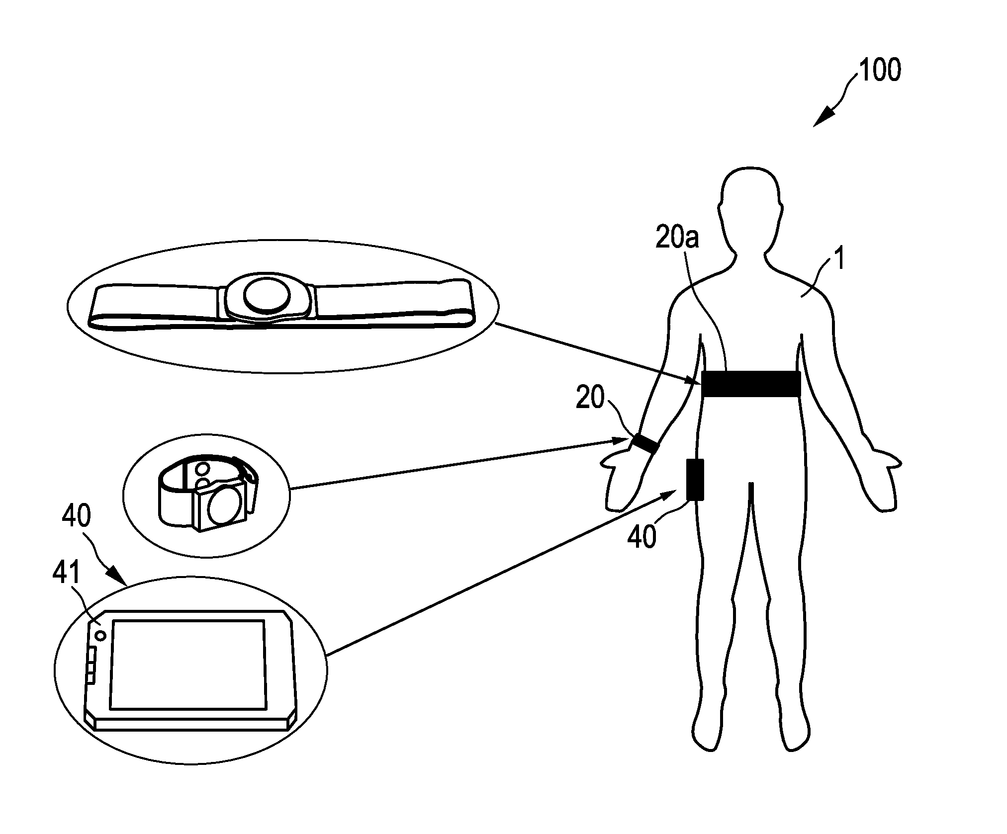
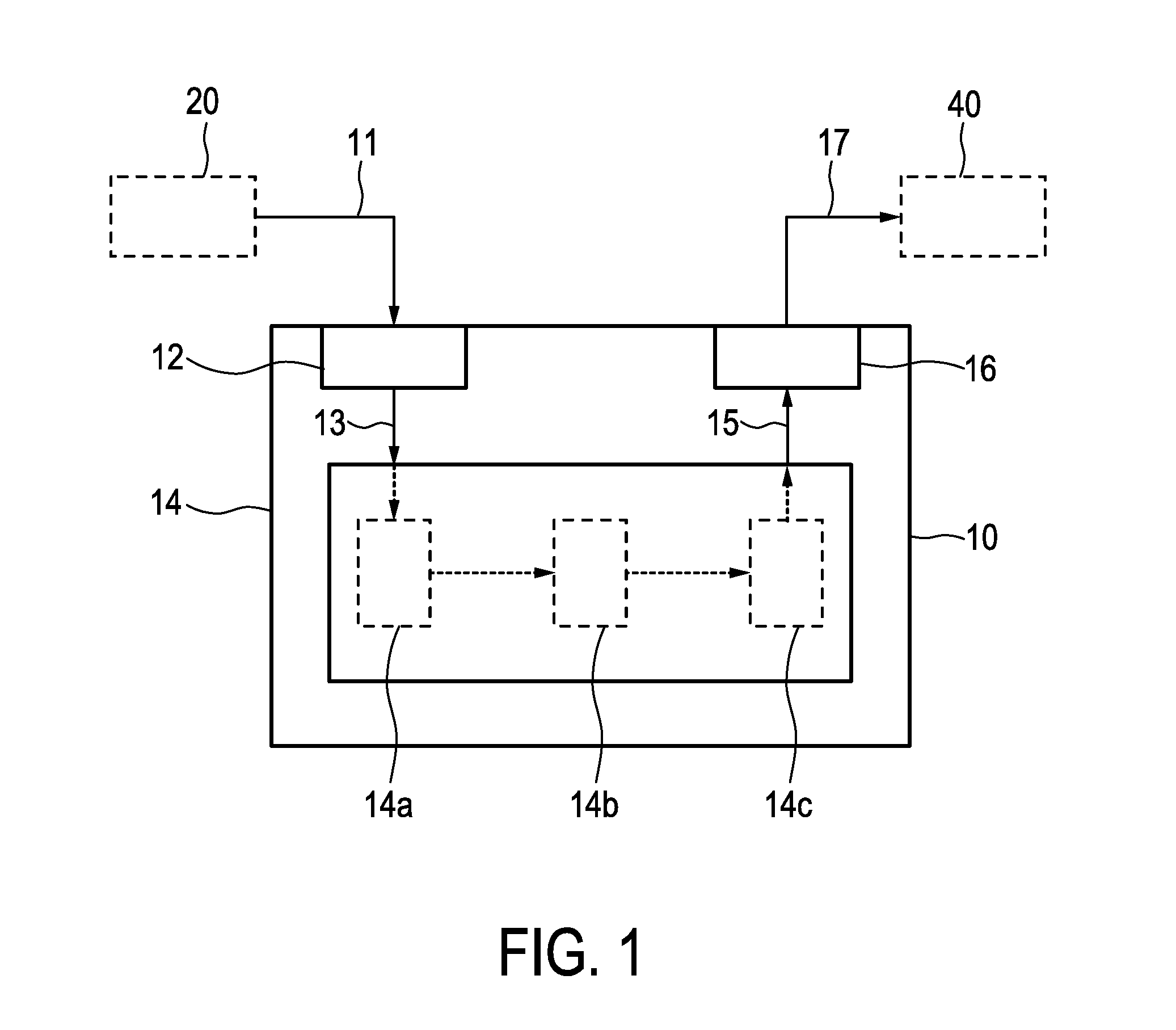
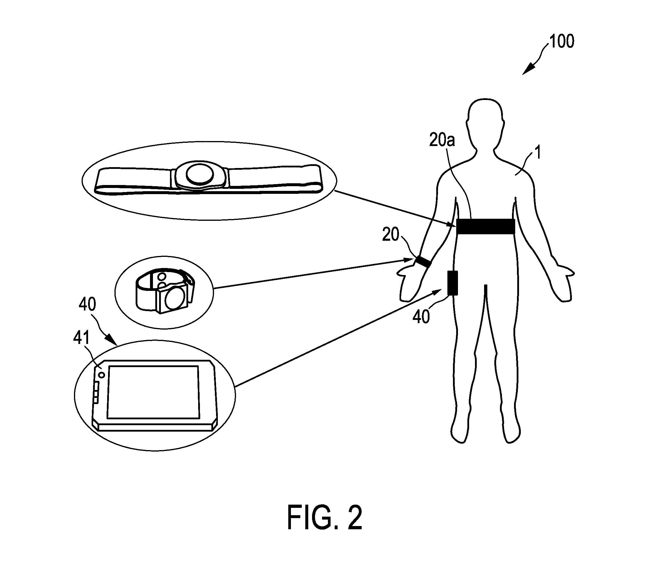
[0037]FIG. 1 shows a schematic diagram of a stress-measuring device 10 according to an embodiment, in particular a long-term stress measuring device. The stress-measuring device 10 comprises an input interface 12 for receiving a skin conductance signal 11 indicating the skin conductance of the user 1. For example, a skin conductance sensor 20 can sense the skin conductance of a user 1 and provide the corresponding skin conductance signal 11 to the input interface 12. The skin conductance signal 11 over time forms skin conductance trace data 13. For example, the stress-measuring device 10 can comprise a memory (not shown in FIG. 1) where the received skin conductance signal is stored over time to produce skin conductance trace data 13.

[0038]The stress-measuring device is in particular used to determine a level 15 of long-term stress (in the following simply referred to as stress level 15). Thus, the stress-measuring device 10 can be adapted to form the skin conductance trace data 13 ...


PUM


Abstract

The present invention relates to a stress-measuring device (10) and method for determining a level (15) of stress of a user (1), in particular long-term stress. The stress-measuring device (10) comprises an input interface (12) for receiving a skin conductance signal (11) indicating the skin conductance of the user (1), the skin conductance signal (11) over time forming skin conductance trace data (13). The stress-measuring device (10) further comprises a processing unit (14) for processing the skin conductance trace data (13), the processing unit (14) adapted to determine, over at least a portion of the skin conductance trace data (13), values of a rise time (tr) between at least two different points of the skin conductance trace data (13), to determine a frequency distribution of the rise time (tr) values, and to determine the level (15) of stress of the user (1) based on the determined frequency distribution.

Description

FIELD OF THE INVENTION[0001]The present invention relates to a stress-measuring device and method for determining a level of stress of a user, in particular long-term stress. The present invention also relates to a wearable device and a stress-measuring system, each comprising such stress-measuring device. Further, the present invention relates to a computer program implementing such stress-measuring method.BACKGROUND OF THE INVENTION[0002]Skin conductance is known as a measure for short-term effective reactions, such as emotions. In this sense, skin conductance is typically analyzed using the phasic component of the skin conductance signal, having rises and falls of duration in the order of seconds.[0003]For example the article “Effect of movements on the electrodermal response after a startle event” by J. Schumm, M. Bachlin, C. Setz, B. Arnrich, D. Roggen and G. Tröster, Second International Conference on Pervasive Computing Technologies for Healthcare, 2008, pages 315-318, disclo...

Claims


Application Information

Patent Timeline
Patent Type & Authority Applications(United States)
IPC IPC(8): A61B5/053A61B5/00A61B5/021
CPCA61B5/0531A61B5/72A61B5/6802A61B5/021A61B5/0533A61B5/165A61B5/681A61B5/7235A61B5/6831A61B5/02055A61B5/02405A61B5/053A61B5/16
Inventor DE VRIES, JAN JOHANNES GERARDUSOUWERKERK, MARTIN
Owner KONINKLIJKE PHILIPS ELECTRONICS NV
Why Eureka
Try Eureka