Abnormality diagnosis apparatus for cooling system

a cooling system and abnormal diagnosis technology, applied in lighting and heating apparatus, fire alarms, instruments, etc., can solve the problems of not being able to precisely detect tampering with the radiator, and having an apparatus configuration that makes it difficult to conduct tampering,

Inactive Publication Date: 2014-02-06
TOYOTA JIDOSHA KK
View PDF0 Cites 3 Cited by
  • Summary
  • Abstract
  • Description
  • Claims
  • Application Information

AI Technical Summary

Benefits of technology

[0014]According to the above configuration, it is possible to perform the abnormality diagnosis of the cooling system based on the temperature characteristic of the cooling portion and the temperature characteristic of the non-cooling portion during the flowing of the coolant. The cooling portion is formed in the component of the cooling system and includes the internal flow path for flowing the coolant, and the non-cooling portion is formed in the component and includes the closed flow path obtained by partially closing the internal flow path. According to the configuration with the cooling portion and the non-cooling portion, a clear difference between the temperature characteristics thereof is generated. Therefore, it is possible to provide the abnormality diagnosis apparatus for the cooling system that uses such a difference between the temperature characteristics.
[0016]After the start of the flowing of the coolant, the temperature of the cooling portion and the temperature of the non-cooling portion converge to respective specific temperatures. However, since the non-cooling portion includes the closed flow path formed by partially closing the internal flow path, the non-cooling portion has the structure in which heat of the coolant is less likely to be conducted. Consequently, the convergence temperature of the non-cooling portion is lower than the convergence temperature of the cooling portion. In this point, according to the above configuration, it is possible to perform the abnormality diagnosis of the cooling system based on the convergence temperature difference. Therefore, it is possible to detect the abnormality of the cooling system with high probability.
[0022]According to the above configuration, since it is possible to close the closed flow path with the material having the thermal conductivity lower than that of the material used for the internal flow path, it becomes possible to generate the above-described difference between the temperature characteristics while minimizing a reduction in the cooling capability of the cooling system caused by the closing.
[0024]According to the above configuration, since it is possible to close the closed flow path with the material having the thermal expansion coefficient higher than that of the material used for the internal flow path, it is possible to expand the closing material as compared with the surrounding material for the internal flow path during the rise of the temperature of the cooling system. Therefore, it is possible to prevent formation of a gap in the closed flow path.

Problems solved by technology

However, a temperature measurement test conducted by the inventors indicated a possibility that it was not possible to precisely detect tampering with the radiator with such an apparatus configuration.
Accordingly, the development of the apparatus having the configuration that makes it difficult to conduct tampering has been required.

Method used


Image

  • Abnormality diagnosis apparatus for cooling system
  • Abnormality diagnosis apparatus for cooling system
  • Abnormality diagnosis apparatus for cooling system

Examples


first embodiment

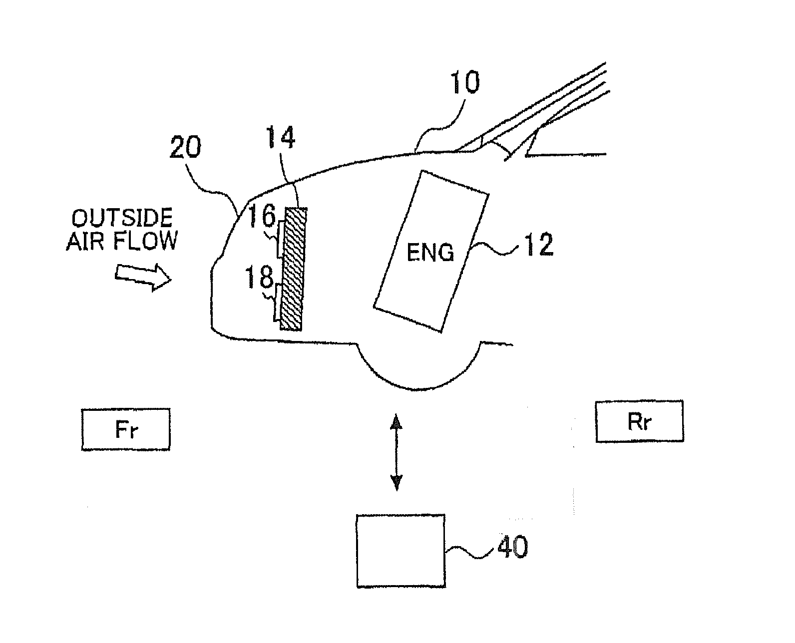
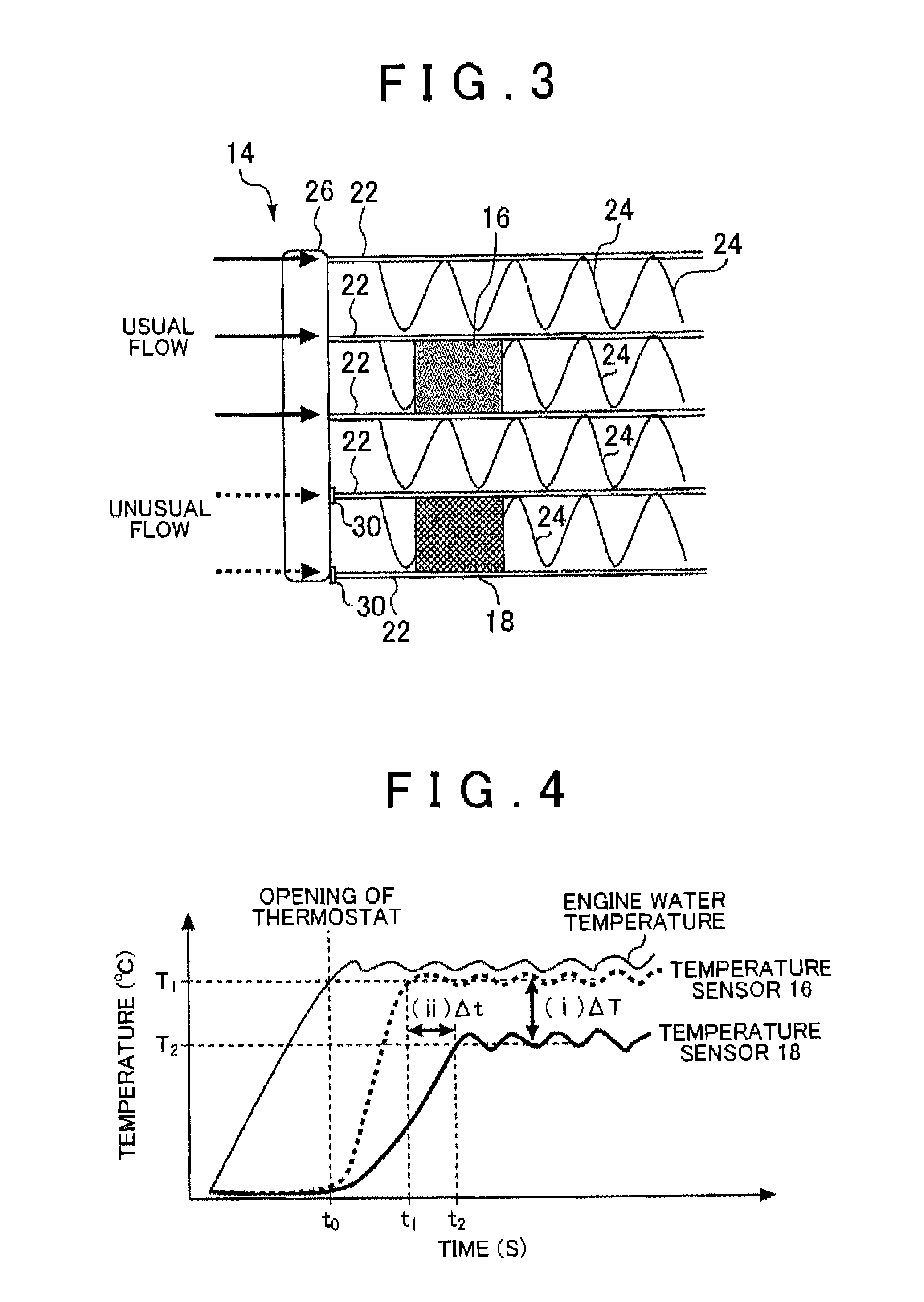
[0049]Next, with reference to FIG. 5, the specific method of the above tampering diagnosis will be described. FIG. 5 is a flowchart showing the tampering diagnosis process executed by the ECU 40 in the Note that the routine shown in FIG. 5 is assumed to be periodically executed repeatedly in synchronization with the valve opening timing of the thermostat (preferably the first valve opening timing after the start of the engine).

[0050]In the routine shown in FIG. 5, first, the ECU 40 determines whether or not a diagnosability condition is satisfied (step 100). Specifically, the ECU 40 determines whether or not the sensor error of the temperature sensor 16 or 18 is detected. In a case where the sensor error is not detected, the ECU 40 determines that the diagnosability condition is satisfied. Consequently, the ECU 40 advances to step 110. On the other hand, in a case where the sensor error is detected, the ECU 40 determines that the diagnosability condition is not satisfied. Consequen...

second embodiment

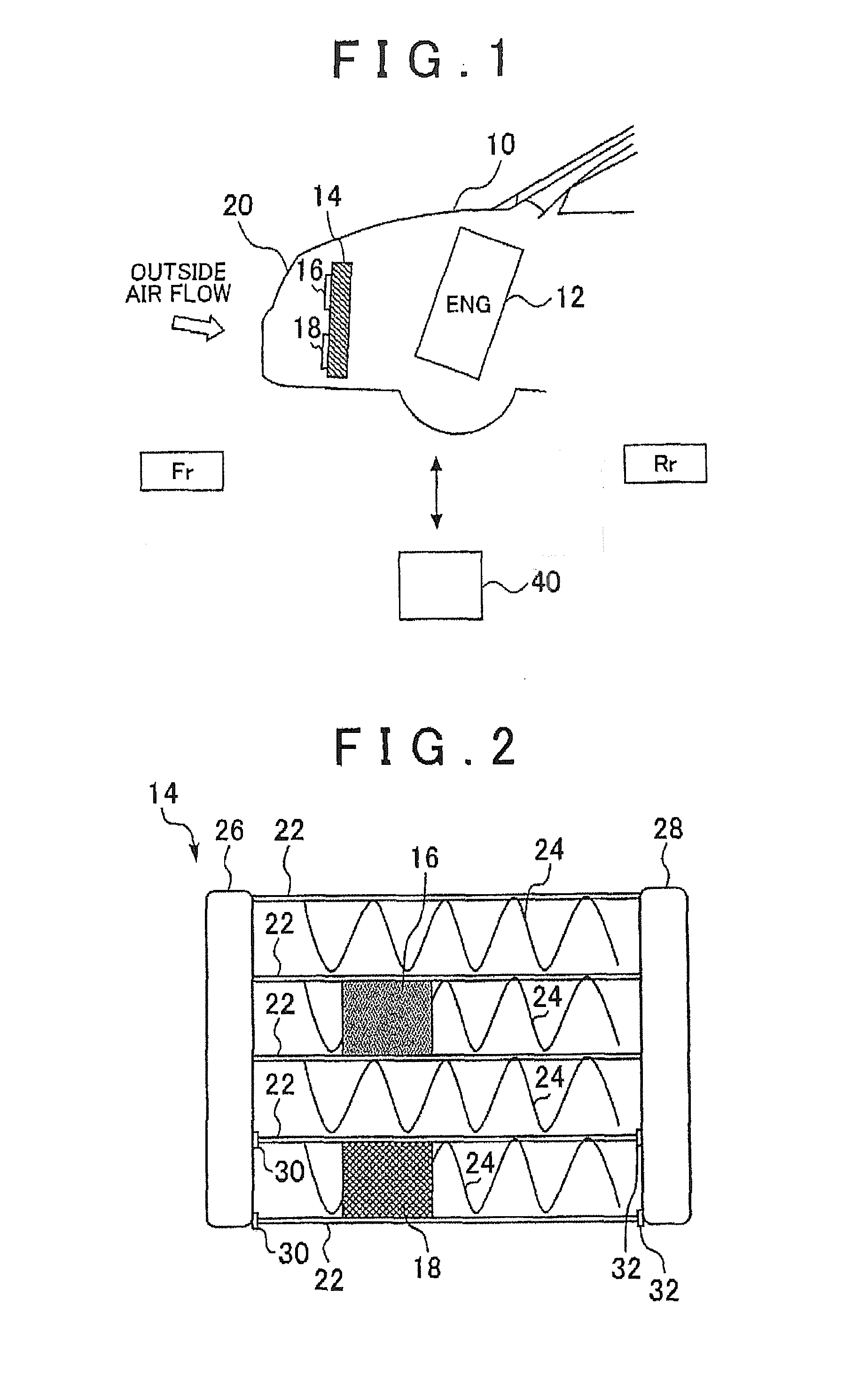
[0073]Note that, in the second embodiment described above, the header tank 28 corresponds to the “common flow path” of the fourth aspect of the invention.

[0074]Next, a third embodiment of the invention will be described. The present embodiment is characterized in that the closed portions 30, 32 of the first embodiment are formed of a material that has a low thermal conductivity such as a silicon bond or the like, and has a thermal expansion coefficient higher than that of the material used for the core of the radiator 14. Consequently, in the following, only this characteristic material will be described, and the description of the configuration of the abnormality diagnosis apparatus and the configuration of the vehicle on which the abnormality diagnosis apparatus is amounted will be omitted.

[0075]In a case where the closed portions 30, 32 are formed of the material having the low thermal conductivity, it becomes possible to generate the difference in temperature characteristic desc...


PUM

PropertyMeasurementUnit
temperatureaaaaaaaaaa
convergence temperatureaaaaaaaaaa
thermal conductivityaaaaaaaaaa

Abstract

An abnormality diagnosis apparatus for a cooling system includes a cooling portion that is formed in the component of the cooling system and has an internal flow path for flowing a coolant, a non-cooling portion that is formed in the component and has a closed flow path obtained by closing at least a part of the internal flow path, and an abnormality diagnosis portion that performs abnormality diagnosis of the cooling system based on temperature characteristics of the cooling portion and temperature characteristics of the non-cooling portion during flowing of the coolant.

Description

INCORPORATION BY REFERENCE[0001]The disclosure of Japanese Patent Application No. 2012-174142 filed on Aug. 6, 2012 including the specification, drawings and abstract is incorporated herein by reference in its entirety.BACKGROUND OF THE INVENTION[0002]1. Field of the Invention[0003]The invention relates to an abnormality diagnosis apparatus for a cooling system.[0004]2. Description of Related Art[0005]Conventionally, there is available a direct ozone reduction (DOR) system in which a catalyst capable of reducing ozone is provided in a vehicle-mounted cooling system represented by, e.g., a radiator, and ozone in air is directly reduced during running of the vehicle. In addition, in the DOR system mentioned above, there is available an apparatus for diagnosing the presence or absence of the illicit modification (what is called tampering) of the above cooling system.[0006]As the apparatus for diagnosing the presence or absence of tampering, for example, U.S. Pat. No. 7,567,884 disclose...

Claims


Application Information

Patent Timeline
Patent Type & Authority Applications(United States)
IPC IPC(8): G01N25/72
CPCG01N25/72F28F27/00F28D1/05366F28D2021/0094F28D2001/028
Inventor SHINODA, YOSHIHISASUGIMOTO, KAZUHIROTANAKA, HIROSHI
Owner TOYOTA JIDOSHA KK
Why Eureka
Try Eureka