Moving object recognition systems, moving object recognition programs, and moving object recognition methods

Active Publication Date: 2014-02-06
DENSO IT LAB +1
View PDF20 Cites 77 Cited by
  • Summary
  • Abstract
  • Description
  • Claims
  • Application Information

AI Technical Summary

Benefits of technology

[0042]With this structure, it is possible to alert the driver in accordance with the risk of a moving object colliding with the vehicle.
[0043]In the moving object recognition system, the collision risk calcu

Problems solved by technology

In the moving object recognition system, the collision risk calculating unit may make the risk higher

Method used


Image

  • Moving object recognition systems, moving object recognition programs, and moving object recognition methods
  • Moving object recognition systems, moving object recognition programs, and moving object recognition methods
  • Moving object recognition systems, moving object recognition programs, and moving object recognition methods

Examples


Example

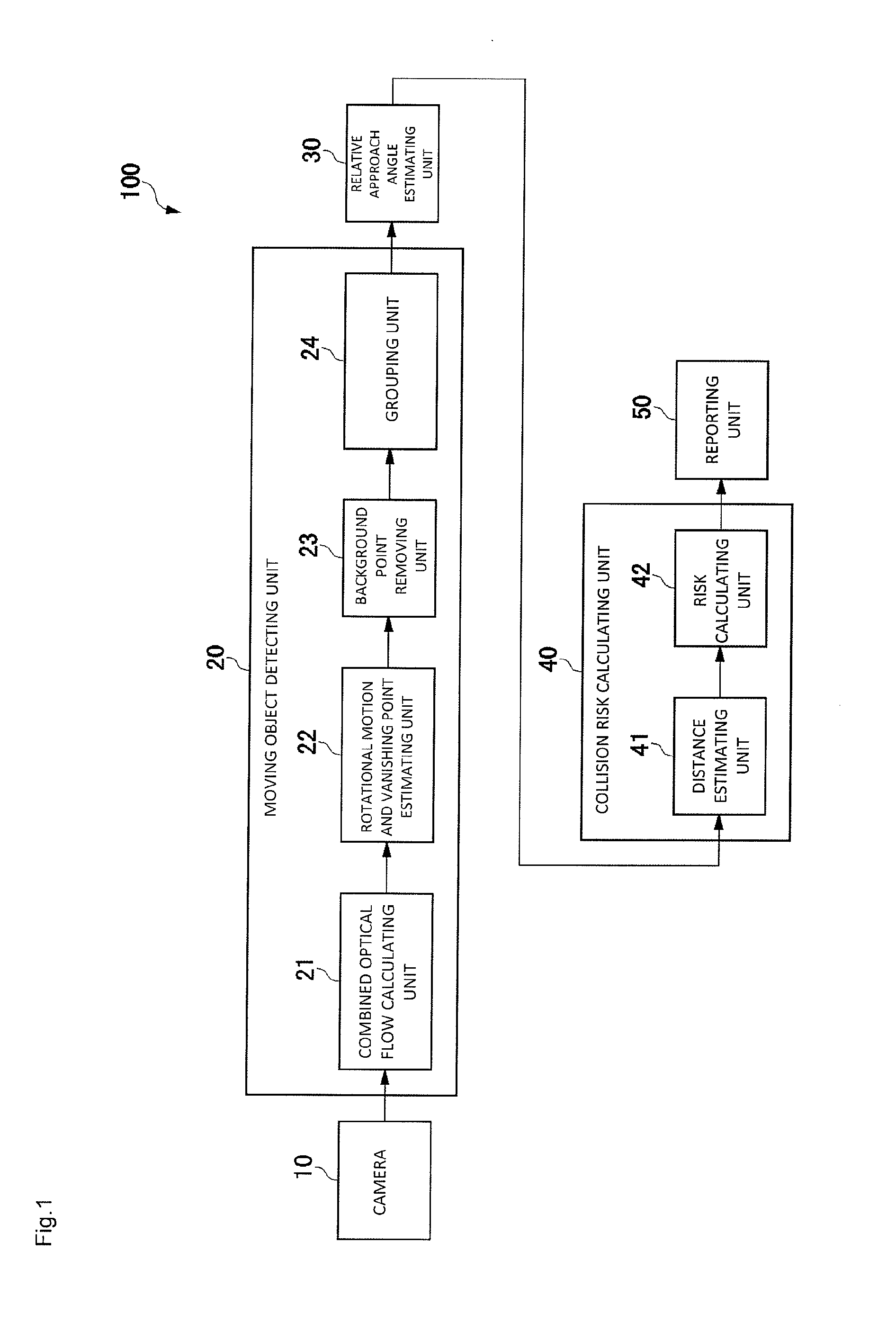
[0076]The following is a description of a moving object recognition system according to an embodiment of the present invention, with reference to the accompanying drawings. FIG. 1 is a block diagram showing the structure of the moving object recognition system according to the embodiment of the present invention. The moving object recognition system 100 of this embodiment is a system that calculates the risk of a moving object colliding with its own vehicle, and reports the risk to the driver. The moving object recognition system 100 includes a camera 10, a moving object detecting unit 20, a relative approach angle estimating unit 30, a collision risk calculating unit 40, and a reporting unit 50. The structure formed with the moving object detecting unit 20, the relative approach angle estimating unit 30, and the collision risk calculating unit 40 is realized by a computer executing a moving object recognition program of the embodiment of the present invention. The moving object rec...


PUM


Abstract

The moving object recognition system includes: a camera that is installed in a vehicle and captures continuous single-view images; a moving object detecting unit that detects a moving object from the images captured by the camera; a relative approach angle estimating unit that estimates the relative approach angle of the moving object detected by the moving object detecting unit with respect to the camera; a collision risk calculating unit that calculates the risk of the moving object colliding with the vehicle, based on the relationship between the relative approach angle and the moving object direction from the camera toward the moving object; and a reporting unit that reports a danger to the driver of the vehicle in accordance with the risk calculated by the collision risk calculating unit.

Description

CROSS REFERENCE TO RELATED APPLICATION[0001]The disclosure of Japanese Patent Application No. 2012-169709, filed on Jul. 31, 2012, is incorporated herein by reference.BACKGROUND OF THE INVENTION[0002]1. Field of the Invention[0003]The present invention relates to moving object recognition systems, moving object recognition programs, and moving object recognition methods for recognizing moving objects by using single-view images.[0004]2. Description of the Related Art[0005]There have been known moving object recognition systems that recognize moving objects existing near a vehicle, and then report to or alert the driver or automatically perform braking on the vehicle (hereinafter referred to simply as “reporting”). The distance from the vehicle to a moving object can be directly measured by using a distance sensor such as a millimeter-wave radar, or can be measured by performing image processing with a stereo camera. The moving direction of the moving object and the velocity of the m...

Claims


Application Information

Patent Timeline
IPC IPC(8): G08G1/16G06K9/00
CPCG06K9/00805G08G1/166G06V20/58
Inventor SATO, IKUROTAMATSU, YUKIMASAGOTO, KUNIHIRO
Owner DENSO IT LAB
Why Eureka
Try Eureka