Clamping Retractor Assembly

a retractor and assembly technology, applied in the field of retractor assemblies, can solve the problems of unsatisfactory free end cantilever, complex mechanism that may need to be employed, and the stability of the retractor may also be a problem, so as to improve the mechanical advantage of the retractor

Inactive Publication Date: 2014-02-06
RETROSPINE
View PDF4 Cites 18 Cited by
  • Summary
  • Abstract
  • Description
  • Claims
  • Application Information

AI Technical Summary

Benefits of technology

[0014]The present applicant has previously described devices to improve mechanical advantage for retraction using bone fixation combined with mechanisms to allow retractor blade rotation.

Problems solved by technology

This creates mechanical disadvantage and complex mechanisms may need to be employed to overcome tissue resistance—i.e. the tendency or bias of a wound towards closure.
As most retractors operate from the wound surface, the distance from the wound surface to the point of contact between retractor blades and the tissue works similar to a vertical cantilever which is suboptimal for the surgeon's requirement for access to the site and also a free end cantilever is not ideal as there is significant force applied at the free end of the retractor by soft tissue.
Also the known mechanisms occupy space restricting the surgeons access and they may also be complex.
The stability of the retractor may also be a problem.
Some dual or multi bladed retractors apply spreading forces against the wound edges to stabilize retractors but these apply force that may potentially injure tissues unnecessary for the purpose of exposure but in order to gain retractor stability.
Stability is desirable but tissue injury is not.
An alternative solution is to use table mounted mechanisms with long mechanical arms but these have great mechanical inefficiency because of the distance from point of fixation i.e. the table, to the point of at which retraction pressure is applied distally.
This problem of the difficulty in applying force and retractor instability is worse the deeper the wound and especially when deep structures require refraction.
Retracting the psoas muscle posteriorly to expose the lateral or anteriolateral spine can be problematic because of the size of the muscle and the depth of the wound.
At L45 from a lateral approach this is made even harder because the iliac crest commonly impedes true lateral access for the retractors and instruments, meaning an oblique approach to the spinal disc may be required.
In many spinal operations the retractors lack stability e.g. with deep multi bladed retractors and various forms of tubular refractors.
The blind needle passage may also damage nerves within the psoas muscle.
Threading a needle in a wound is fiddly, threads passing through retractor tissues have less stability than a handle.
Threads passed through a muscle cannot be repositioned easily.
These known surgical retraction methods currently all lead to retractors working at considerable mechanical disadvantage.

Method used


Image

  • Clamping Retractor Assembly
  • Clamping Retractor Assembly
  • Clamping Retractor Assembly

Examples


Embodiment Construction

[0072]The examples referred to herein are illustrative and are not to be regarded as limiting the scope of the invention. While various embodiments of the invention have been described herein, it will be appreciated that these are capable of modification, and therefore the disclosures herein are not to be construed as limiting of the precise details set forth, but to avail such changes and alterations as fall within the purview of the description.

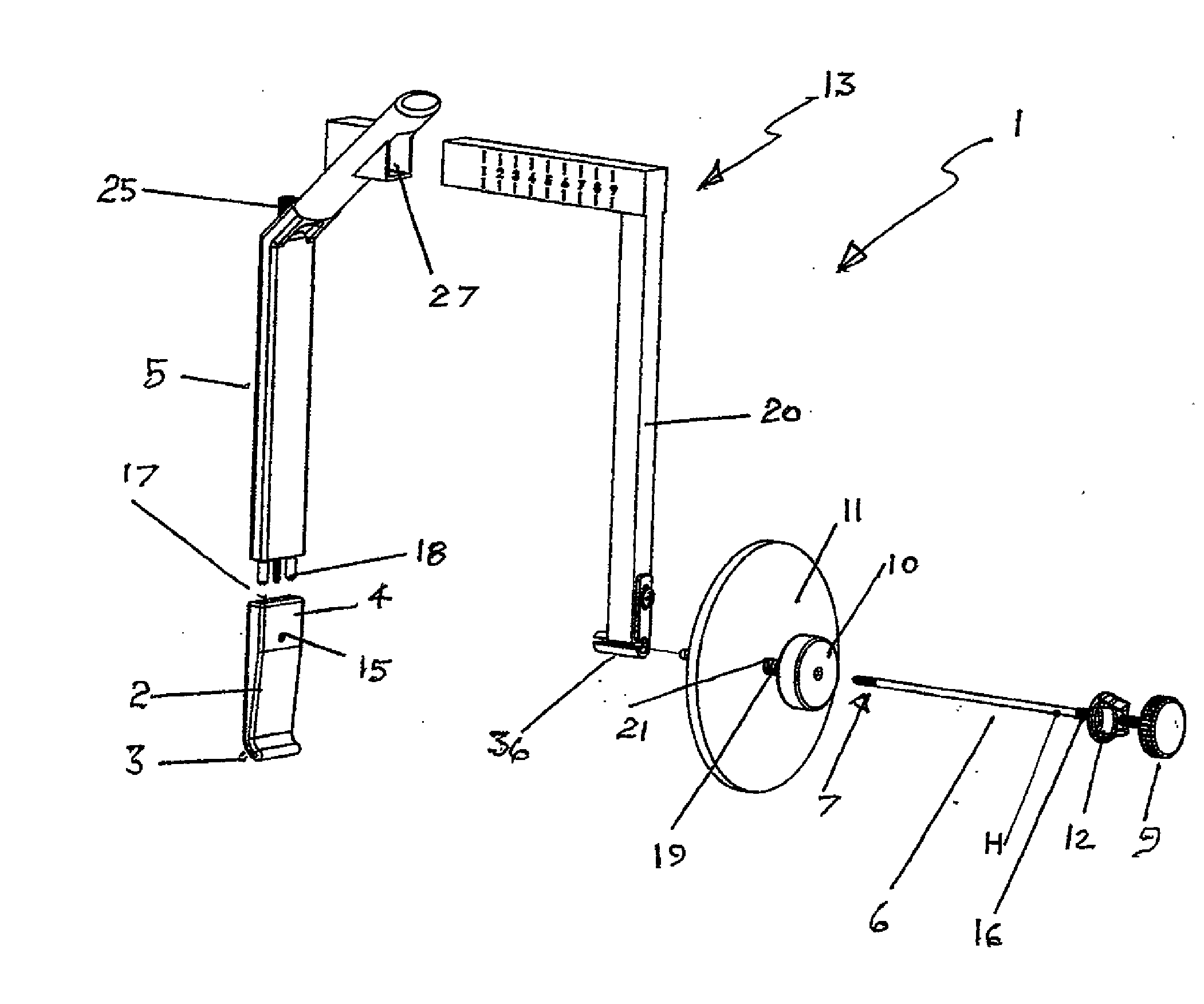
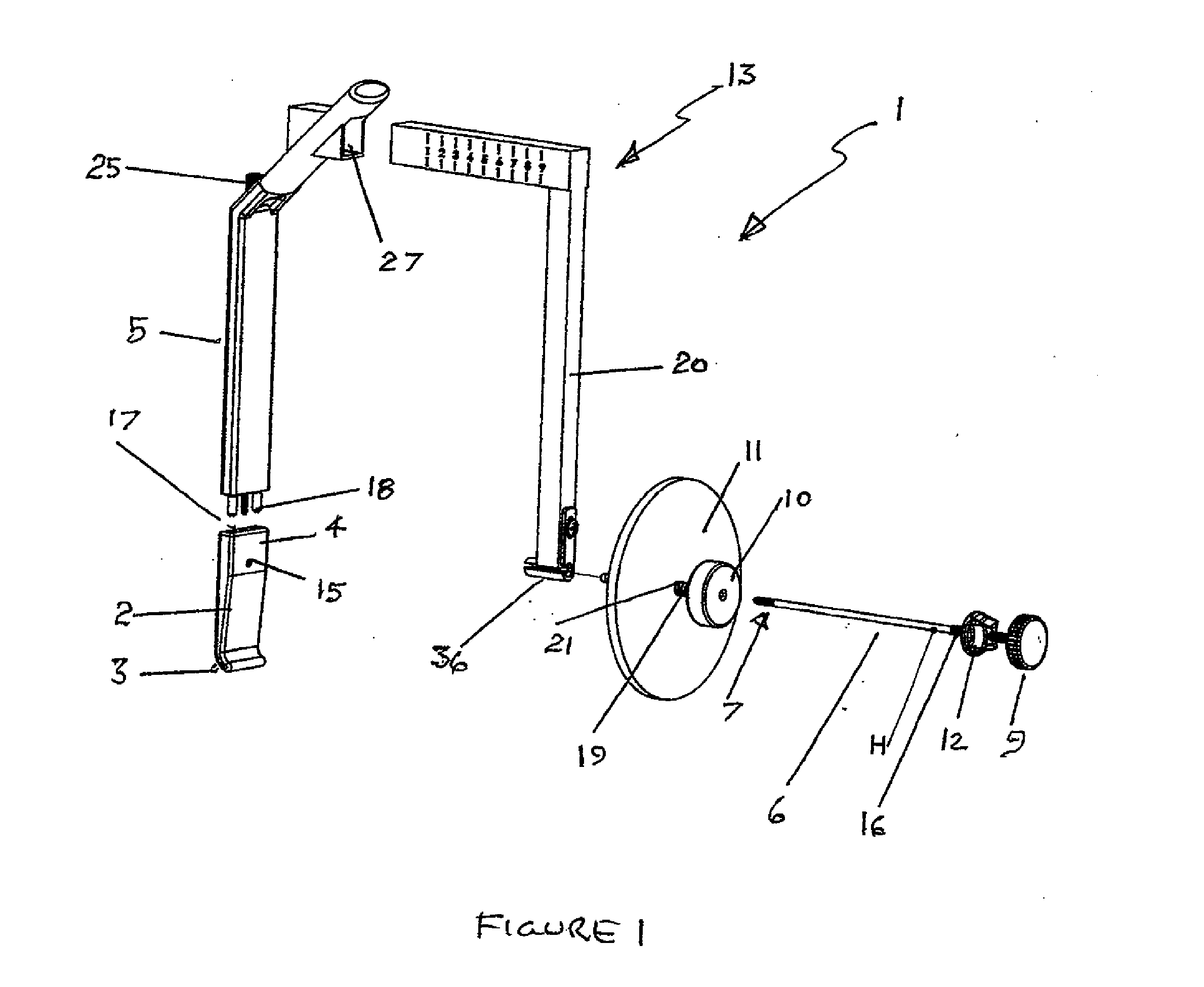
[0073]FIG. 1 shows a perspective view of a retraction assembly 1 according to one embodiment. Assembly 1 for refracting soft tissue in a surgical wound comprises a retractor blade 2 having a first distal end 3 and a second end 4 which includes an associated handle 5. Assembly 1 further comprises a one piece trochar handle 6 having a pointed tip first end 7 which engages blade 2 and a second end 8 which includes a manual operating control element 9. Intermediate therebetween is adjustable stop 10 which engages a plate 11, wherein the plate e...


PUM


Abstract

An assembly for retracting soft tissue in a surgical incision, the assembly comprising; a supporting member having first and second ends; a refractor blade having a first distal end and a second proximal end retained at the first end of the support member; a retaining arm which co operates with the support member and receives and supports a clamping assembly; an adjusting assembly which engages the support member and allows the clamping assembly to advance and retract relative to the retractor blade.

Description

BACKGROUND [0001]The present invention relates to retraction assemblies and more particularly relates to assemblies for retracting soft tissue during surgery and particularly during spinal surgery. The invention further relates to a G clamp retractor which has an internal component which engages a wound to retract soft tissue and an external component which has the capacity to set and control the degree of retraction. The invention further relates to an assembly which more efficiently retracts the psoas muscle to allow access to spinal vertebrae.PRIOR ART[0002]In the field of surgery, conventional retractors used in applications such as spinal surgery include a retractor blade portion that is in contact with the soft tissues and a handle portion that controls the blade position. The blades are inserted into position through the surgical wound. The direction of force applied by the blades to keep the wound open is usually at right angles to this line of entry. This creates mechanical...

Claims


Application Information

Patent Timeline
Patent Type & Authority Applications(United States)
IPC IPC(8): A61B17/02A61B17/08
CPCA61B17/08A61B17/02A61B17/3403A61B2017/00991A61B2017/3405A61B2017/3492A61B2017/00407A61B2017/00349A61B2017/00862A61B90/06A61B2090/062
Inventor SEEX, KEVINFRY, DONALD
Owner RETROSPINE
Why Eureka
Try Eureka