Acoustic palpation using non-invasive ultrasound techniques for identification of target sites and assessment of chronic pain disorders

a non-invasive, target site technology, applied in the direction of diagnostic recording/measuring, application, therapy, etc., can solve problems such as abnormalities or enlarged areas, and achieve the effects of reducing exposure to ionizing radiation, effective transmission of ultrasound to tooth surfaces, and highly sensitive localization of tooth decay

Inactive Publication Date: 2014-02-06
PHYSIOSONICS +1
View PDF13 Cites 11 Cited by
  • Summary
  • Abstract
  • Description
  • Claims
  • Application Information

AI Technical Summary

Benefits of technology

[0021]A single acoustic stimulation, when applied repeatedly within frequency band of 1-20 Hz can produce an increasing number of action potentials within the spinal cord, referred to as “windup.” Such a repeated stimulus can also produce more intense sensation, described as “temporal summation.” Administration of targeted acoustic palpations (e.g., iFU) using methods and systems of the present invention provides a non-invasive methodology for inducing wind-up and temporal summation when applied in deep tissue. The use of targeted acoustic palpations to stimulate deep tissue sites has the advantage of eliminating, or significantly reducing, concomitant stimulation of skin and shallow subcutaneous tissue, which may present confounding factors when stimulation protocols employ electrical, thermal or mechanical stimulation, for example, which are generally far less targeted in their stimulatory effects.
[0022]Methods and systems of the present invention may thus also be used in the assessment and treatment of patients with chronic pain syndromes, such as fibromyalgia and other myofascial pain syndromes. Application of iFU can induce temporal summation at tissue sites, and can be used to identify both the presence of central sensitization and peripheral sources when sub-clinical stimulation is applied to the sensitized receptive field. Application of focal acoustic (ultrasound) palpations of an appropriate magnitude, frequency, intensity, duration and / or pulse repetition rate to target site(s) in patients suffering from chronic pain may be used to localize and / or map the site(s) of pain generation, providing an assessment of the location and scope of a sensitized receptive field. Application of focal acoustic (ultrasound) palpations of an appropriate magnitude, frequency, intensity, duration and / or pulse repetition rate to target site(s) in patients suffering from chronic pain may provide an evidence-based conclusion and, perhaps, a definitive diagnosis of a chronic pain disorder.
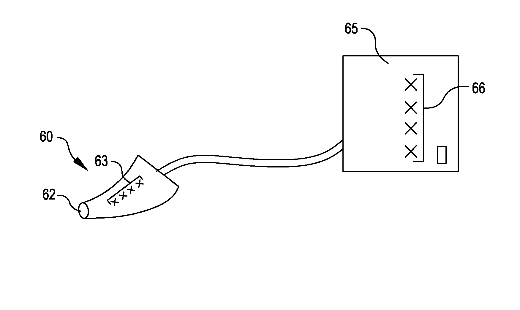
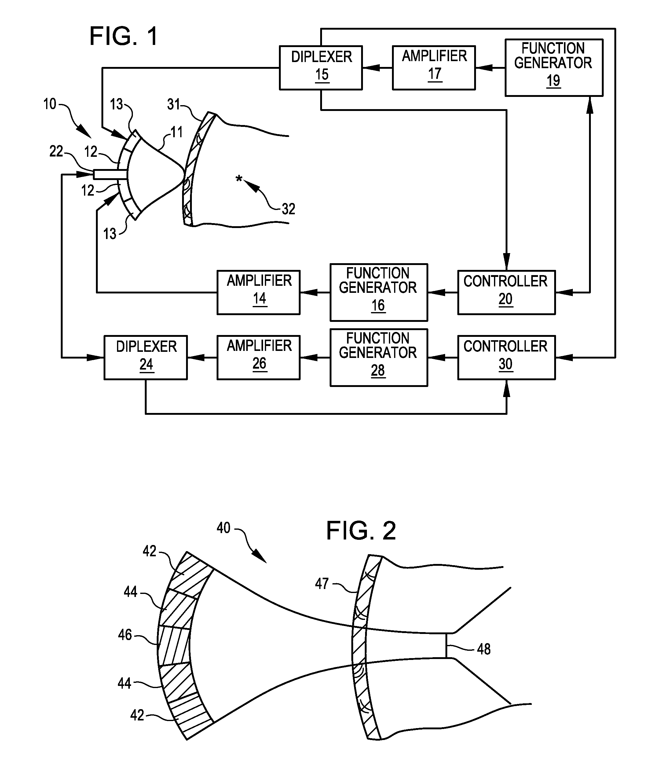
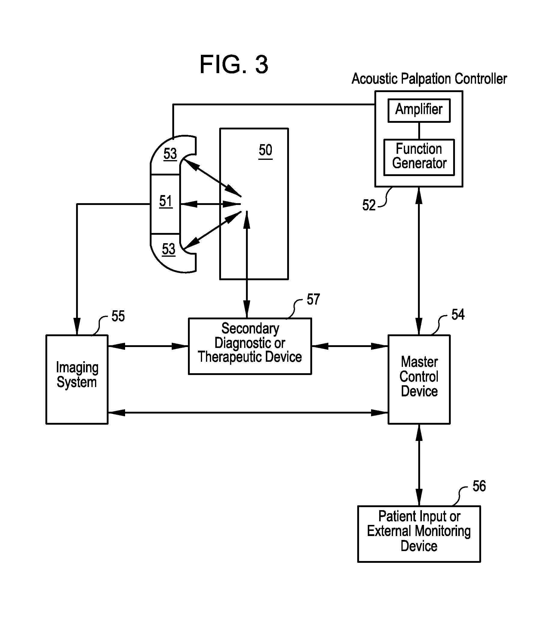
[0029]In another embodiment, multiple intense focused ultrasound beams may be provided from a collocated source, or from multiple sources. In this embodiment, multiple independent or independently controllable sources of intense focused ultrasound may be used to palpate tissue at a desired target site by converging the multiple beams at selected target site(s). This may improve the accuracy of targeted probing and allow delivery of higher energy intense focused ultrasound palpations to target sites without affecting surrounding tissue. In one embodiment, multiple ultrasound transducers, each capable of delivering acoustic doses sufficient to administer intense focused ultrasound pulse palpations, provide a desired intense focused ultrasound acoustic dose by combined coincident focus at a target site. Multiple ultrasound transducers (or arrays) having multiple or independently adjustable focal points may be housed in a single, integrated probe housing, or multiple transducers (or arrays) having multiple or independently adjustable focal points may be provided in multiple separate probes. Multiple probes may be adapted for manual (clinician) placement and holding, or multiple probes may be mounted on moveable mechanical structures, such as arms, that may be manipulated to position the one or more probes at desired body surfaces for probing selected target sites. The probes may be adjustable in three dimensions to facilitate placement on different body sites, and automated spatial adjustment and positioning of the probes to interrogate programmed or programmable or selectable body locations may be provided under the control of a system controller.
[0031]Another application of targeted acoustic probing of the present invention is the detection of dental caries. Acoustic probes having interfaces that effectively transmit ultrasound to tooth surfaces and internal tooth structures are used in this application. Such acoustic probes may have flexible interfaces that are capable of conforming to the surface conformations of teeth to provide positioning of the acoustic probe and application of intense focused ultrasound at various tooth locations. While incipient caries may not be painful absent targeted acoustic palpation, application of acoustic radiation forces to decayed teeth and tooth structures, is expected to evoke pain sensations or other sensations indicative of tooth decay. Diagnostic screening using acoustic palpation in the place of dental X-rays would reduce exposure to ionizing radiation and may provide more highly sensitive localization of tooth decay.
[0032]In yet another application, targeted acoustic probing as described herein is used to localize nerves and other sensitized tissues for guidance of needles or other delivery devices and delivery of anesthesia and / or analgesic and / or therapeutic agents to nerve sites and other sensitized sites. In this application, targeted acoustic probing may be applied to tissue sites in proximity to a nerve or another sensitized tissue site to identify the spatial location of nerves and sensitized sites. Because targeted acoustic probing may be administered non-invasively and is generally considerably less painful than the electrical probes (e.g., electrical needles) often used to locate nerve sites prior to administration of compositions, this application offers significant advantages compared to current nerve localization methods.

Problems solved by technology

In many circumstances, a tissue site may not be terribly painful, but it may be enlarged or otherwise abnormal.

Method used


Image

  • Acoustic palpation using non-invasive ultrasound techniques for identification of target sites and assessment of chronic pain disorders
  • Acoustic palpation using non-invasive ultrasound techniques for identification of target sites and assessment of chronic pain disorders
  • Acoustic palpation using non-invasive ultrasound techniques for identification of target sites and assessment of chronic pain disorders

Examples


example 1

[0095]A prototype image-guided intense focused ultrasound palpation device was constructed, as illustrated in FIG. 4B. It consisted of a high intensity focused ultrasound (HIFU) transducer coupled with a diagnostic ultrasound probe from an Acuson diagnostic ultrasound device. The prototype device was used by the investigator to generate transient sensations in normal tissue in the palm of his hand using short, sharp but energetically small bursts of ultrasound. The following acoustic protocol evoked transient sensations of pain: a single pulse of 10 ms in duration at a frequency of 1.1 Mhz and spatial peak, time average intensity of approximately 10 W / cm2. The investigator did not perceive any lasting effects of the ultrasound application.

example 2

[0096]Experimental studies were conducted in an animal model to evaluate whether probing a sensitive tissue with intense focused ultrasound (iFU) produced detectable sensitivity. The prototype ultrasound transducer device consisted of a commercial piezo-electric, flat transducer built into a solid, cylindrical cone shaped aluminum housing having a flat distal face. The dimensions of the housing allowed ultrasound emitted from the transducer to have its focus at the proximal tip of the aluminum housing. The focus of the device was characterized with a needle hydrophone to measure the spatial peak and temporal peak intensity (I_sptp) as described in Miao et al. (2005). The focus of the experimental iFU device was about the size of a grain of rice, extending less than a centimeter from the transducer head with a width of less than half a centimeter onto and into the adjoining tissue. It was not necessary to provide image guidance of the focused ultrasound device, since the focal point ...

example 3

[0106]An experimental protocol was developed to demonstrate that intense focused ultrasound (iFU) can detect peripheral neuropathic pain in the extremity of an animal model of pain. Partial sciatic nerve ligations (pSNL, protocol described in Seltzer et al., 1990 Z. Seltzer, R. Dubner and Y. Shir, A novel behavioral model of neuropathic pain disorders produced in rats by partial sciatic nerve injury, Pain 43 (1990), pp. 205-218) were performed on one group of Sprague Dawley rats on one of their two hind paws, thereby sensitizing that paw.

[0107]The prototype iFU device consisted of a commercial piezo-electric, flat transducer built into a solid, cylindrical cone shaped aluminum housing whose dimensions allowed the ultrasound emitted from the transducer to have a focus at the proximal tip of the aluminum housing. The focus of the device was characterized with a needle hydrophone to measure the spatial peak and temporal peak intensity (I_sptp), as described in Miao et al. (2005). The f...


PUM


Abstract

Methods and systems for identifying and spatially localizing tissues having certain physiological properties or producing certain biological responses, such as the sensation of pain, in response to the application of intense focused ultrasound (acoustic probing or palpation) are provided. In some embodiments, targeted acoustic probing is employed to identify the scope and severity of chronically painful sensitized tissue areas, and of chronic pain disorders. In other applications, targeted acoustic probing is used to localize nerves and other sensitized tissues for guidance of needles and other delivery devices, and for delivery of anesthetic, analgesic or therapeutic compositions.

Description

REFERENCE TO PRIORITY APPLICATIONS[0001]This application is a continuation of U.S. patent application Ser. No. 13 / 161,214, filed Jun. 15, 2011, which claims priority to U.S. Provisional Patent Application No. 61 / 355,034 filed Jun. 15, 2010 and which is a continuation-in-part of U.S. patent application Ser. No. 12 / 563,060, filed Sep. 18, 2009, which claims priority to U.S. Provisional Patent Application No. 61 / 192,650, filed Sep. 19, 2008. This application is also a continuation-in-part of U.S. patent application Ser. No. 11 / 050,993, filed Feb. 4, 2005, which is a continuation of U.S. patent application Ser. No. 09 / 995,897, filed Nov. 28, 2001 and issued as U.S. Pat. No. 6,875,176 on Apr. 4, 2005, which claims priority to U.S. Provisional Patent Application No. 60 / 253,959, filed Nov. 28, 2000. The disclosures of these priority applications are incorporated by reference herein in their entireties.STATEMENT REGARDING FEDERALLY SPONSORED RESEARCH[0002]Subject matter disclosed in this ap...

Claims


Application Information

Patent Timeline
Patent Type & Authority Applications(United States)
IPC IPC(8): A61B5/00A61B8/00
CPCA61B8/00A61B5/4827A61B5/4824A61B5/4893A61B8/08A61B8/4218A61B8/4472A61B2018/00642A61N7/02A61N2007/0078A61B8/0808A61B8/4494
Inventor JARVIK, JEFFREY G.MOURAD, PIERREKLIOT, MICHELFREDERICKSON, ROBERT C.A.MCCLINTIC, ABBI MDICKEY, TREVOR C.GOFELD, MICHAEL
Owner PHYSIOSONICS
Why Eureka
Try Eureka