Apparatus for antenna weightlessness deployment test

a technology for deployment apparatus and antenna, applied in the direction of instruments, cosmonautic vehicles, transportation and packaging, etc., can solve the problems of incomplete deployment test of reflectors, type is not completely free, and the friction force cannot be avoided, so as to reduce the driving friction force and stop the deployment apparatus smoothly

a technology for deployment apparatus and antenna, applied in the direction of instruments, cosmonautic vehicles, transportation and packaging, etc., can solve the problems of incomplete deployment test of reflectors, type is not completely free, and the friction force cannot be avoided, so as to reduce the driving friction force and stop the deployment apparatus smoothly

US20140041444A1Inactive Publication Date: 2014-02-13ELECTRONICS & TELECOMM RES INST

Image

  • Apparatus for antenna weightlessness deployment test
  • Apparatus for antenna weightlessness deployment test
  • Apparatus for antenna weightlessness deployment test

Examples


Embodiment Construction

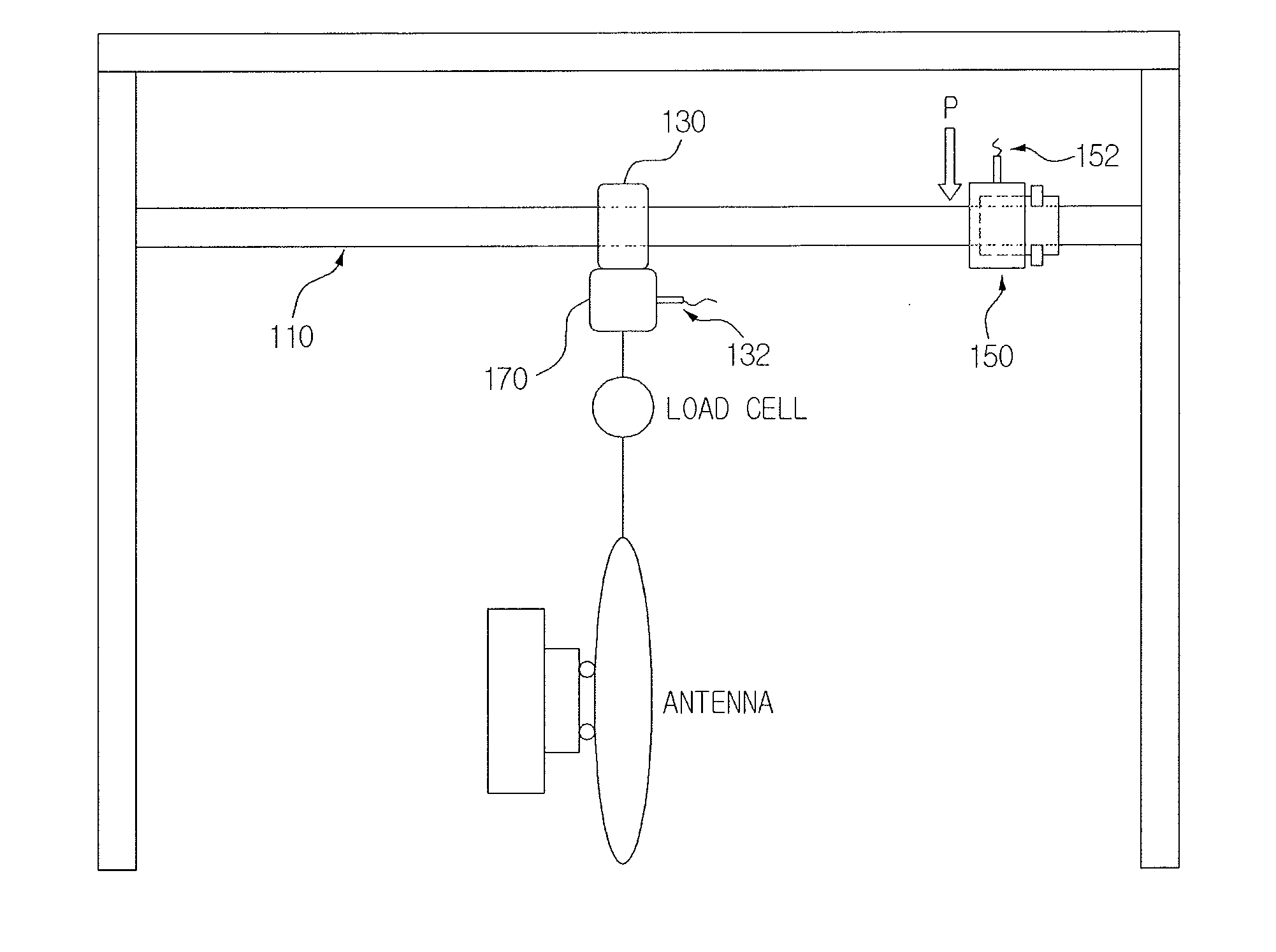
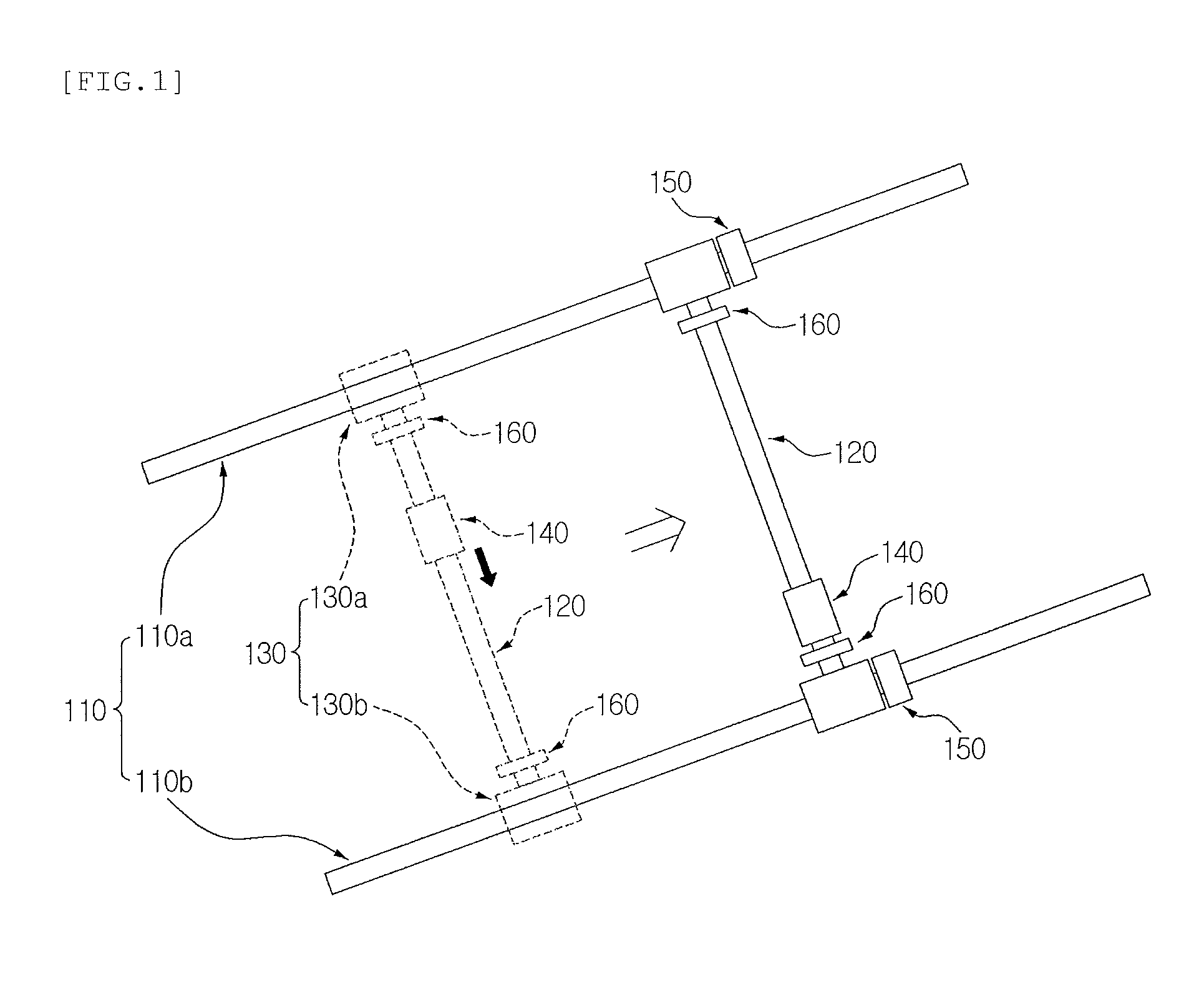
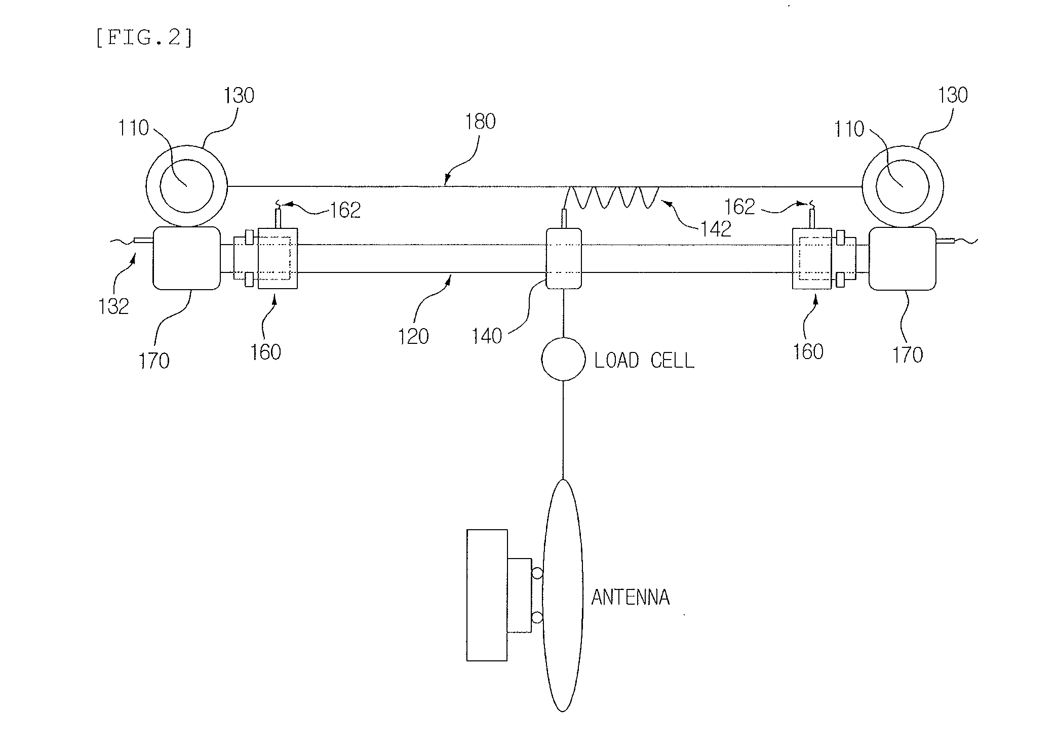
[0033]Hereinafter, an apparatus for an antenna weightlessness deployment test according to an exemplary embodiment of the present invention will be described with reference to FIGS. 1 to 5. Exemplary embodiments of the present invention will be described in detail based on portions necessary to understand the operations and actions of the present invention.

[0034]In particular, the present invention proposes a new apparatus configured to be disposed at both ends of each of a first direction mobile support shaft and a second direction mobile support shaft so that a first direction mobile deployment apparatus and a second direction mobile deployment apparatus, respectively, are supported on a first direction mobile support shaft and a second direction mobile support shaft by an air bearing and stop at a predetermined position using an air pressure at the time of operating the first direction mobile deployment apparatus and the second direction mobile deployment apparatus. Herein, the f...


PUM


Abstract

Disclosed is an apparatus for an antenna weightlessness deployment test. The apparatus for an antenna weightlessness deployment test includes: a pair of first direction mobile support shafts mounted in parallel at a predetermined distance; first direction mobile deployment apparatuses mounted to be supported by an air bearing so as to slidably move on the first direction mobile support shaft; a second direction mobile support shaft mounted to connect the first direction mobile deployment apparatuses with each other; and second direction mobile deployment apparatuses mounted to be supported by an air bearing so as to slidably move on the second direction mobile support shaft.

Description

CROSS-REFERENCE TO RELATED APPLICATIONS[0001]This application claims priority to and the benefit of Korean Patent Application No. 10-2012-0087295 filed in the Korean Intellectual Property Office on Aug. 9, 2012, the entire contents of which are incorporated herein by reference.TECHNICAL FIELD[0002]The present invention relates to an apparatus for an antenna weightlessness deployment test, and more particularly, to an apparatus for an antenna weightlessness deployment test in which a first direction mobile deployment apparatus and a second direction mobile deployment apparatus are each configured to be supported on a first direction mobile support shaft and a second direction mobile support shaft by an air bearing, and the first direction mobile deployment apparatus and the second direction mobile deployment apparatus are configured to be disposed at both ends of each of the first direction mobile support shaft and the second direction mobile support shaft so as to stop at a predeter...

Claims


Application Information

Patent Timeline
13 Feb 2014
Publication
US20140041444A1
IPC
G01M1/00
CPC
B64G1/66; B64G7/00; G01M99/00
Inventors
CHOI, JANG SUP; KWAK, CHANG SOO