Lubrication control apparatus for vehicle in-wheel motor unit

a technology of lubrication control apparatus and in-wheel motor unit, which is applied in the direction of machine/engine, lubrication of auxiliaries, transportation and packaging, etc., can solve the problem of difficult to make a sound shielding countermeasure, and achieve the effect of worsening electric power consumption

Inactive Publication Date: 2014-02-13
NISSAN MOTOR CO LTD
View PDF10 Cites 20 Cited by
  • Summary
  • Abstract
  • Description
  • Claims
  • Application Information

AI Technical Summary

Benefits of technology

[0011]From the viewpoint such that it is basically not necessary for the lubrication of the in-wheel motor unit at the time of the vehicle stop and, while oil is left within a lubrication oil passage even at the low vehicle speed region, the lubrication of the in-wheel motor unit is possible by means of the in-wheel motor unit and the number of rotations of the oil pump may be reduced as low as possible and the oil pumps may be stopped, this idea is embodied. That is to say, it is an object of the present invention to provide a lubrication control apparatus for the in-wheel motor unit for the vehicle which can eliminate the problem of solving the operation sound (noise) of the oil pump(s) in the in-wheel motor unit during the vehicle stop or at the low vehicle speed region and can avoid the worsening of the traveling distance per unit electric power due to a wasteful operation of the oil pump.

Problems solved by technology

Thus, it is difficult to make a sound shielding countermeasure.

Method used


Image

  • Lubrication control apparatus for vehicle in-wheel motor unit
  • Lubrication control apparatus for vehicle in-wheel motor unit
  • Lubrication control apparatus for vehicle in-wheel motor unit

Examples


first embodiment

Structure of a First Embodiment

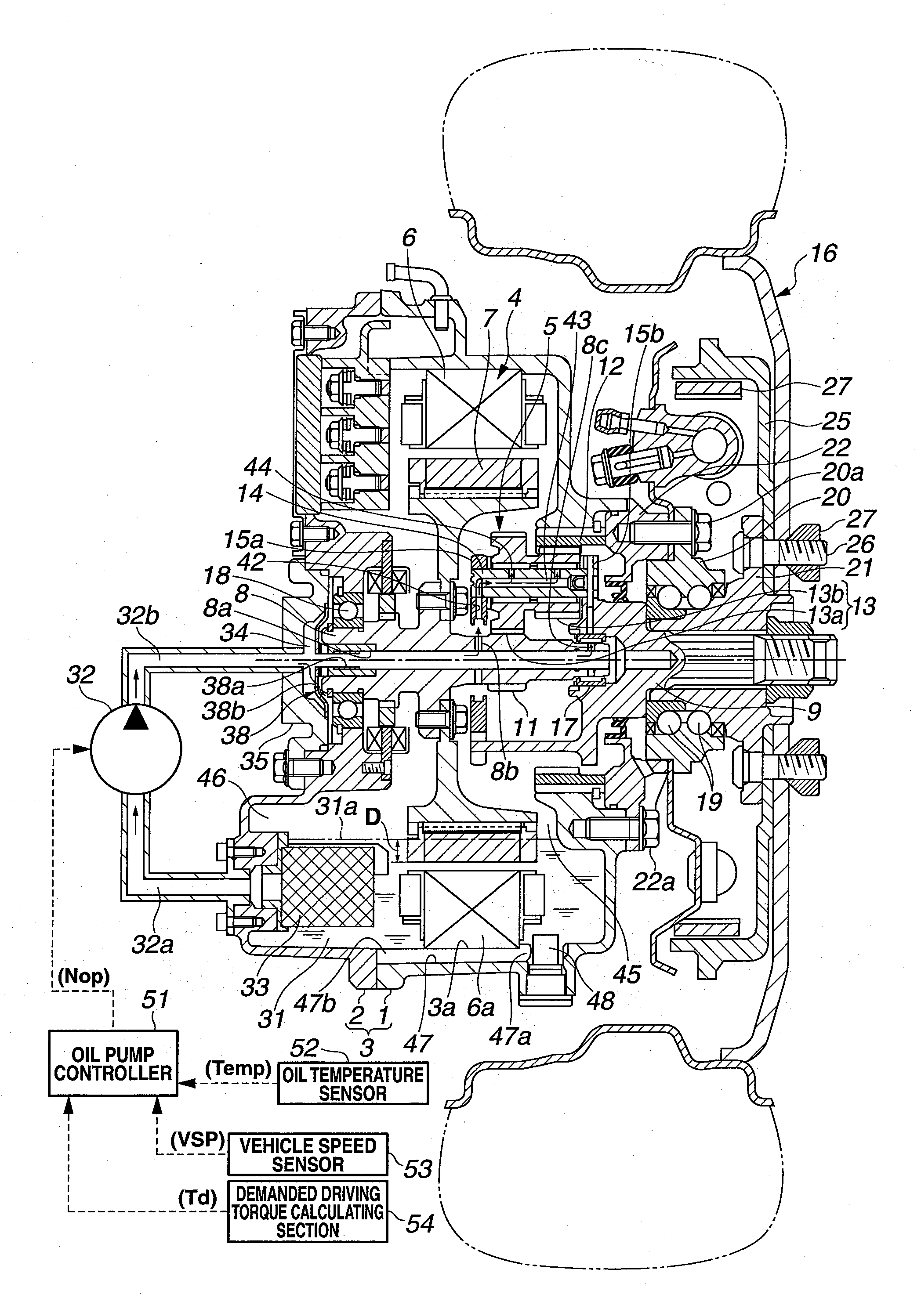
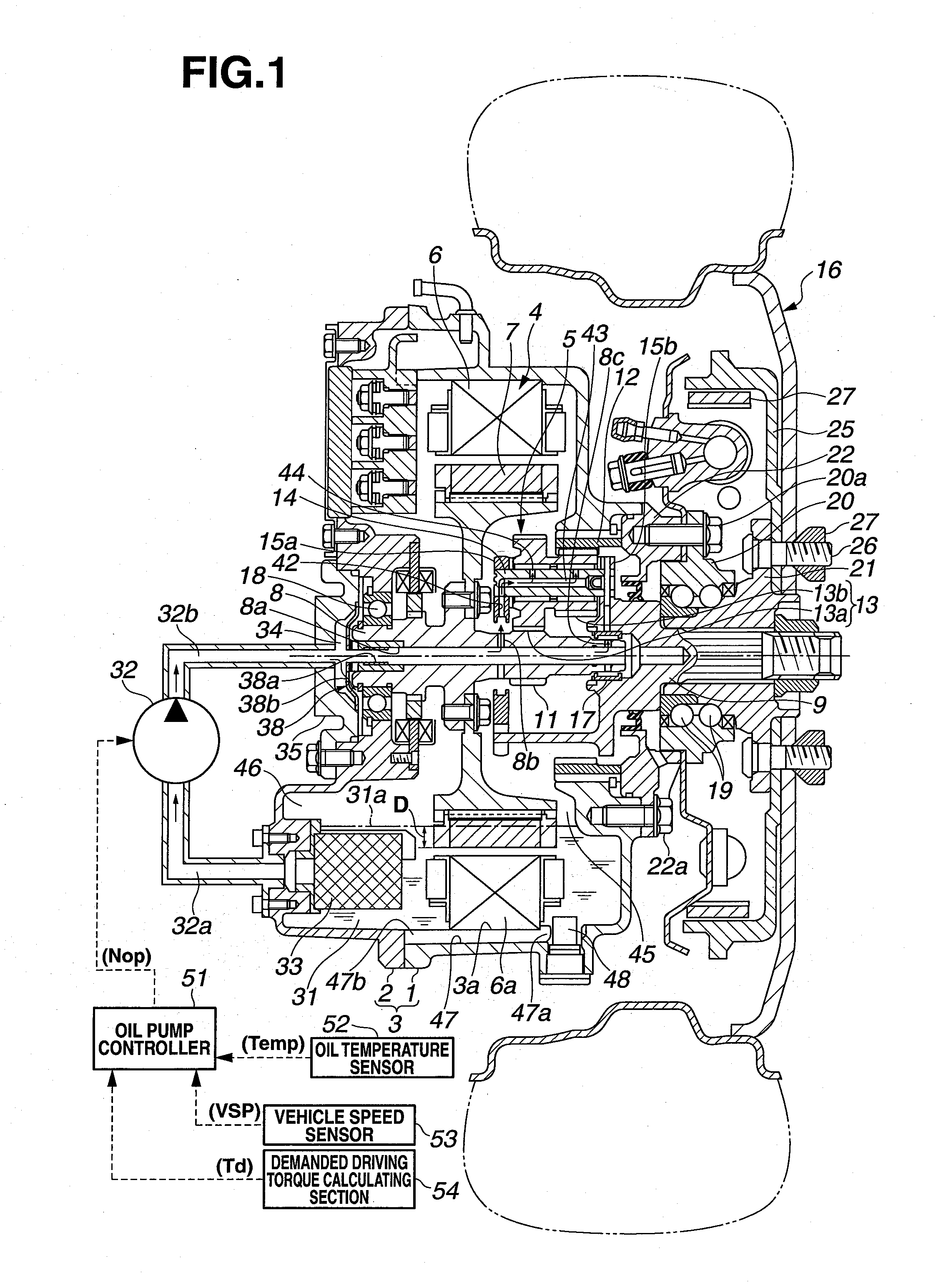
[0027]FIG. 1 shows a longitudinal cross sectional side view representing an in-wheel motor unit in which a lubrication control apparatus in a first preferred embodiment according to the present invention is equipped.

In FIG. 1, reference numeral 1 denotes a case main frame of an in-wheel motor unit, reference numeral 2 denotes a rear cover of a case main frame 1, a unit case 3 of an in-wheel motor unit is formed by means of a mutual uniting of a case main frame 1 and a rear cover 2.

[0028]In-wheel motor unit shown in FIG. 1 houses an electrically driven motor 4 and a planetary gear type speed reduction gear set 5 (hereinafter, referred simply as to a speed reduction gear set) within a unit case 3. Electrically driven motor 4 includes: an annular stator 6 which is fitted to an inner circumferential portion of case main frame 1 to be fixed; and a rotor 7 concentrically arranged onto an inner circumferential portion of annular stator 6 with a radial gap.

[00...

second embodiment

Structure of a Second Embodiment

[0101]Next, referring to FIG. 11, a second preferred embodiment according to the present invention will be described with reference to FIGS. 1 to 10. It should be noted that the explanation of a part or parts common to the above-described first embodiment will suitably be omitted.

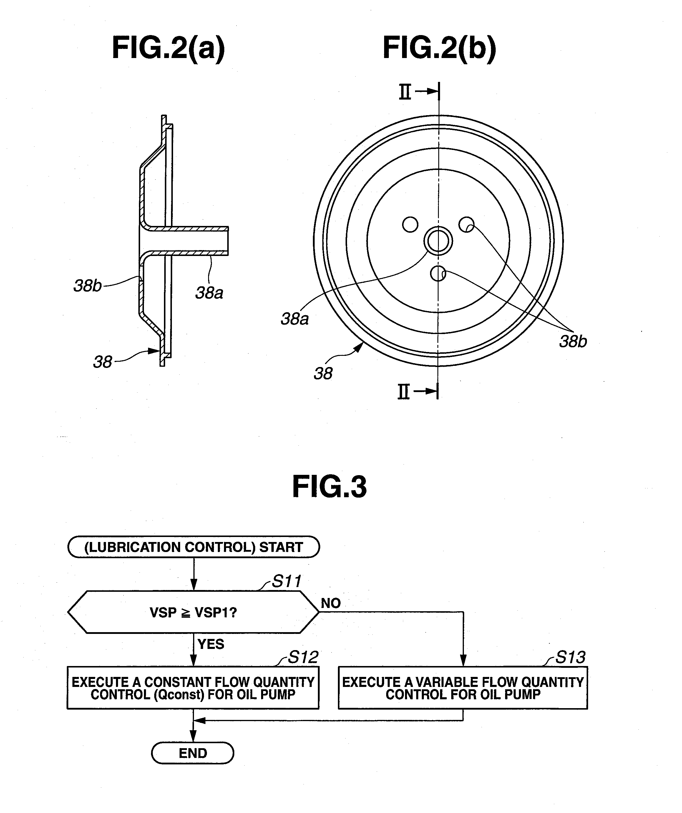
[0102]In this second embodiment, above-described setting torque ΣTdm is a lower limitation value of demanded driving torque Td required to activate (each) oil pump 32 from the vehicle stopped state. Since ΣTd≧ΣTdm, oil suction and supply quantity Q0 during the vehicle stopped state shown in FIG. 5 in a case where oil pump(s) 32 is activated from the vehicle stopped state is made correspondence to the lubrication oil quantity required for the in-wheel motor unit due to the presence of demanded driving torque Td at the time of the vehicle stopped state. Thus, as demanded driving torque Td (its integration value ΣTd) becomes larger (in more details, as a torque difference ΣTd−ΣT...


PUM


Abstract

Each oil pump (32) is drivingly controlled in such a way that, in a low vehicle speed region lower than a set vehicle speed VSP1 at which a stirring resistance by oil within an in-wheel unit case (3) is not in excess of an allowance level, a suction and supply quantity denoted by a solid line characteristic is provided. In other words, the oil pump(s) is stopped until the vehicle speed reaches to a predetermined vehicle speed VSP0 at which a remaining oil within an oil passage is scattered in all directions and becomes disappeared after the start of vehicle in an oil pump stopped state including a vehicle stop at which the lubrication is not necessary.

Description

TECHNICAL FIELD[0001]The present invention relates to a lubrication control apparatus which is useful in a drive unit (hereinafter, referred to as an in-wheel motor unit) for each of road wheels and which is used for an electric automotive vehicle travelable by driving the respective road wheels through individual electrically driven motors.BACKGROUND ART[0002]The in-wheel motor unit is, for example, as shown in a Patent Document 1, provided with a speed reduction gear mechanism such as a planetary gear set in addition to the above-described electrically driven motor and constitutes a single unit to transmit a rotational power from the electrically driven motor to a corresponding one of the road wheels under a speed reduction by means of the above-described speed reduction gear mechanism to drive the corresponding road wheel.[0003]Hence, it is necessary to lubricate the above-described speed reduction gear mechanism in each of the in-wheel motor units.However, a resting of the lubri...

Claims


Application Information

Patent Timeline
Patent Type & Authority Applications(United States)
IPC IPC(8): F01M11/00
CPCF01M11/00B60K7/0007B60K17/046F16H57/0006F16H57/0436F16H57/0486B60K2007/0038B60K2007/0092F16H57/0479F16H57/043F16H57/0426F16H57/0402
Inventor YAMAUCHI, YASUHIRO
Owner NISSAN MOTOR CO LTD
Why Eureka
Try Eureka