Composite insulating panel

Inactive Publication Date: 2014-02-13
KINGSPAN HLDG (IRL) LTD
View PDF12 Cites 16 Cited by
  • Summary
  • Abstract
  • Description
  • Claims
  • Application Information

AI Technical Summary

Benefits of technology

[0025]In one embodiment the raised projections comprise raised crowns. In one case the raised projections are of generally trapezoidal form and extend longitudinally along the length of the panel. The raised projections may co

Problems solved by technology

This casts a shadow which, depending on the angle of incident sunlight, will reduce the solar energy collection efficiency.
Further, the in

Method used


Image

  • Composite insulating panel
  • Composite insulating panel
  • Composite insulating panel

Examples


Embodiment Construction

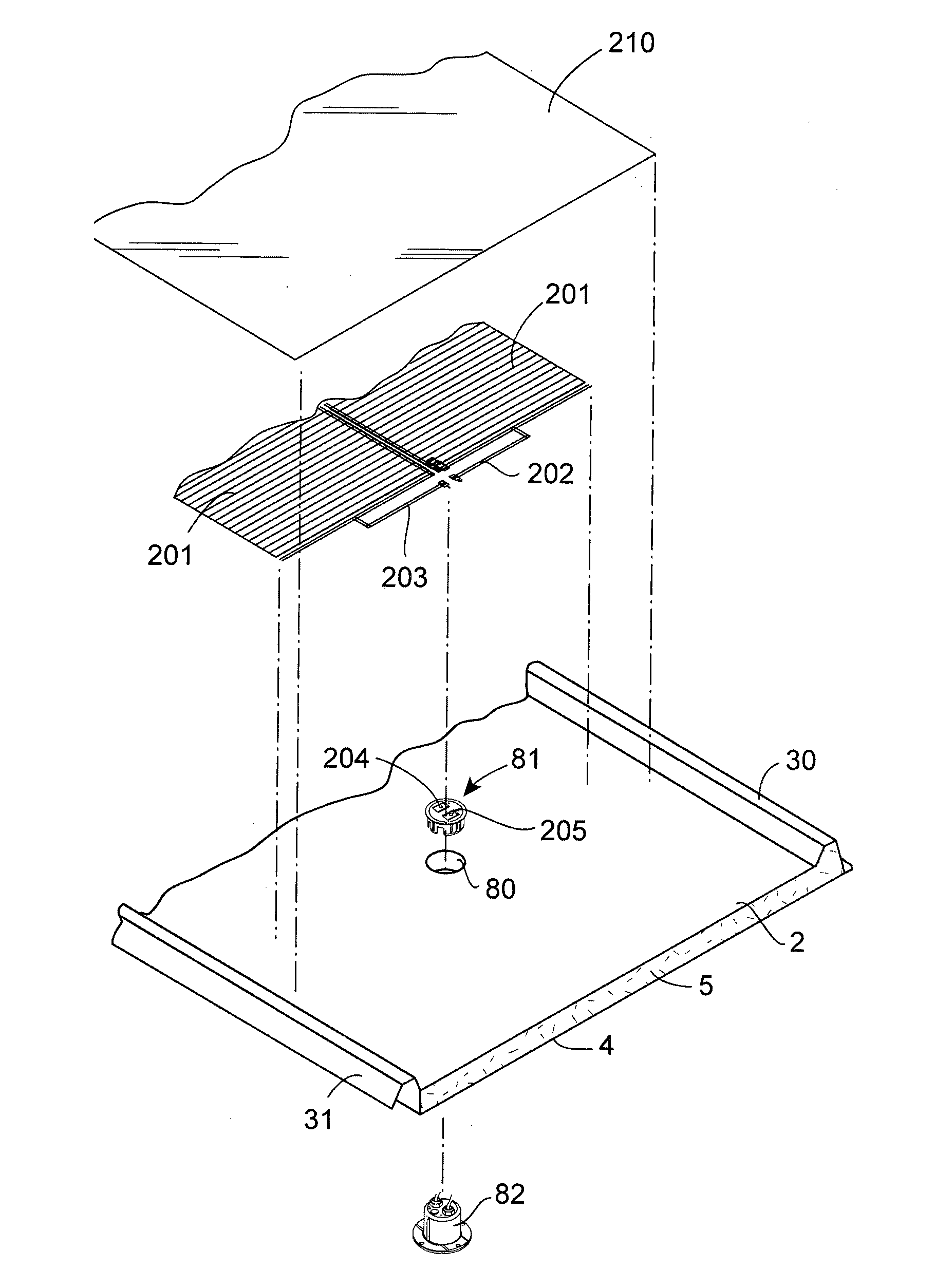
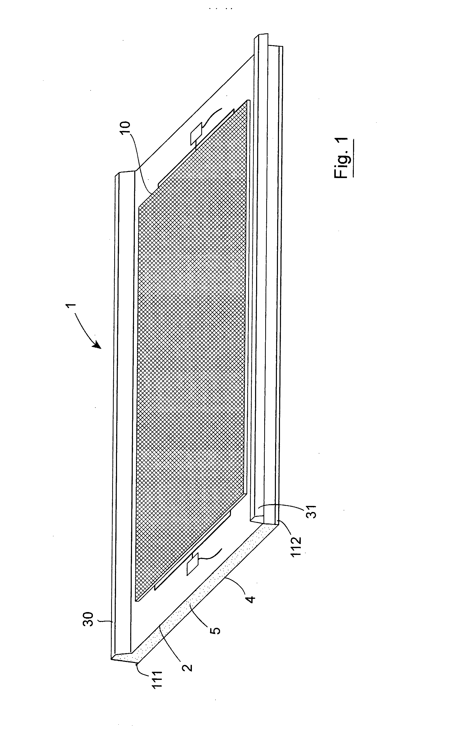
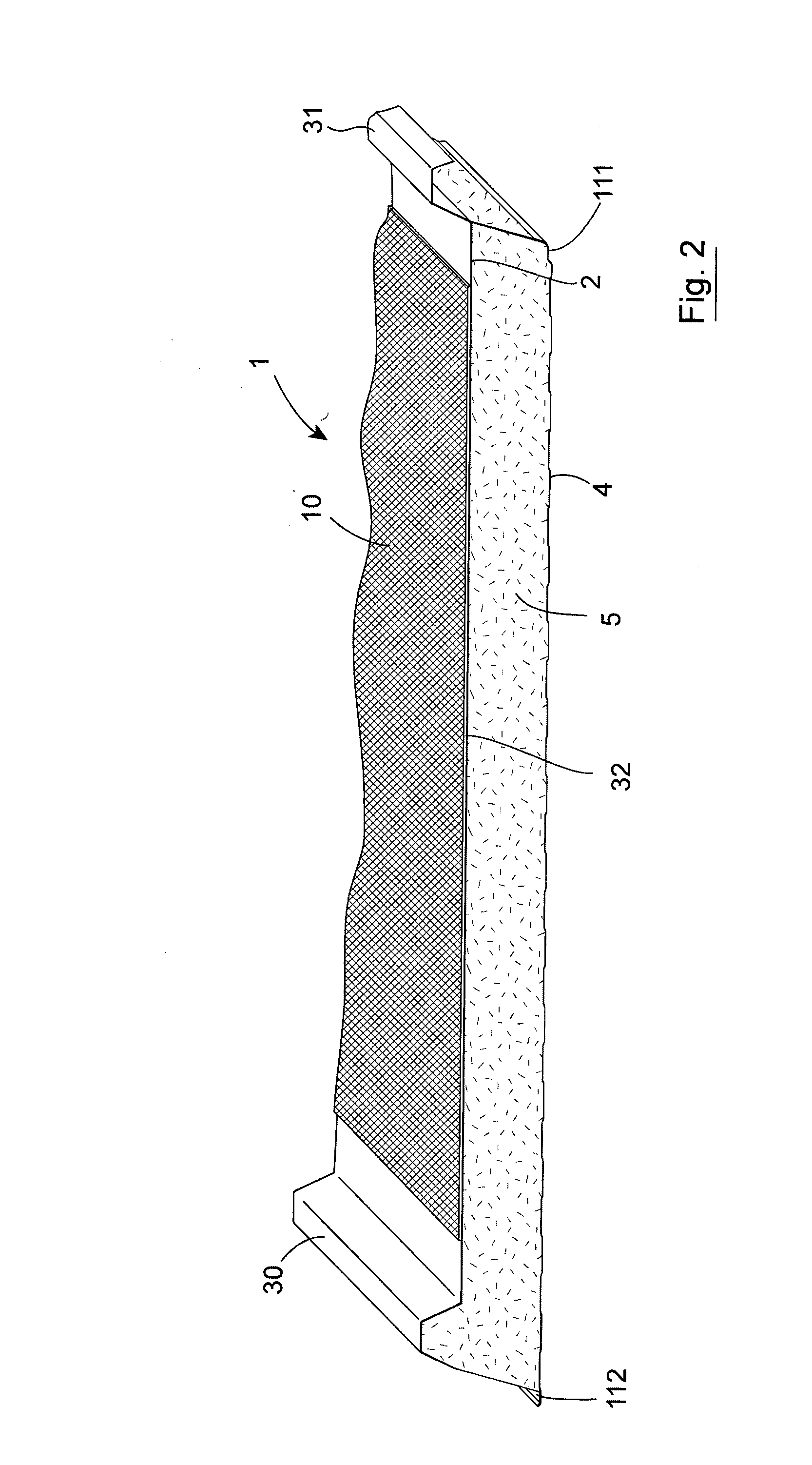
[0070]Referring to the drawings there is illustrated an insulating panel 1 according to the invention which in this case comprises a first or external sheet 2, a second or inner sheet 4 with an insulating body, in this case an insulating foam 5 therebetween. The foam may, for example be a polyisocyanurate foam or a phenolic foam. In this case the panel 1 is a roof panel 1 comprising a profiled external sheet 2 which is typically of metal, such as galvanised steel. The external sheet 2 has a first longitudinally extending raised projection 30 at one side of the panel and a second longitudinally extending raised projection 31 on the opposite side of the panel. The external sheet 2 has a substantially flat portion 32 which extends between the first and second raised projections 30, 31. The raised projections 30, 31 are in the form of crowns which in this case are of generally trapezoidal form and extend longitudinally along the length of the panel. There is a side underlap projection o...


PUM

PropertyMeasurementUnit
Adhesivityaaaaaaaaaa
Metallic bondaaaaaaaaaa
Translucencyaaaaaaaaaa

Abstract

A composite insulating panel comprises an external sheet, an internal sheet, and an insulating body between the sheets. The external sheet has a first longitudinally extending raised side underlap projection at one side and a side overlap projection on the opposite side of the panel with a substantially flat portion extending between the projections. A photovoltaic solar collector is mounted to the flat portion of external sheet. The solar collector comprises a photovoltaic sheet and a protective translucent cover for the photovoltaic sheet. A first adhesive layer is provided between the photovoltaic sheet and the translucent cover. A second adhesive layer is provided between the underside of the photovoltaic sheet and the external surface of the composite panel upper or external sheet.

Description

INTRODUCTION[0001]With increasing energy costs there is a need for a more thermally efficient system for cladding a building.[0002]Various attempts have been made to provide composite insulation panels with photovoltaic material applied. For example, US2002 / 0112419A describes planar photovoltaic elements which are bonded using a cold bonding adhesive to a cover plate of a panel. However, the area for solar energy absorption is reduced by virtue of an intermediate trapezoidal projection between the sides of the panel. This casts a shadow which, depending on the angle of incident sunlight, will reduce the solar energy collection efficiency. Further, the intermediate panel projection also reduces the area to which a solar energy collector can be mounted and presents manufacturing difficulties.[0003]This invention is directed towards providing an improved insulating panel which will address at least some of these issues.STATEMENTS OF INVENTION[0004]According to the invention there is pr...

Claims


Application Information

Patent Timeline
IPC IPC(8): H01L31/048H01L31/18H01L31/05H01L31/042
CPCH01L31/0482H01L31/05H01L31/18H01L31/0422B32B15/046E04C2/292E04D3/352E04D3/358H01L31/02013Y02E10/50H02S20/00H02S20/23H02S40/34H01L31/049Y10T156/10Y02B10/10E04C2/296E04C2/34
Inventor CAROLAN, JAMESFLYNN, GREGORY
Owner KINGSPAN HLDG (IRL) LTD
Why Eureka
Try Eureka