Chilled vehicle fuel storage tank

a fuel storage tank and cold-cooled technology, which is applied in the direction of liquid fuel feeders, machines/engines, transportation and packaging, etc., can solve the problems of more prone to damage to the tubing, and achieve the effects of superior thermal conduction properties, more thermal efficiency, and more protection from damag

Active Publication Date: 2016-11-15
BILLS ANTWANETTE +1
View PDF10 Cites 3 Cited by
  • Summary
  • Abstract
  • Description
  • Claims
  • Application Information

AI Technical Summary

Benefits of technology

[0013]In one embodiment, the invention is comprised of a series of tubing, connected to the vehicle's radiator, and in intimate contact with the vehicle fuel tank. Intimate contact means that the tubing is attached, surface-to-surface with the fuel tank. The tubing can be placed on top of the fuel tank, on the bottom of the fuel tank, on the side of the fuel tank, or a combination of the top, bottom, and side of the fuel tank. The tubing will be more thermally efficient when placed on the bottom of the fuel tank, or on the side of the fuel tank, because the liquid gasoline or diesel fuel will be on the bottom of the fuel tank. Liquid fuel has superior thermal conduction properties when compared with the vapor at the top of the tank. However, the tubing will be more protected from damage when placed on the top of the fuel tank. All of the placements, bottom, side, top, or a combination of all of them, will allow the tubing to cool the bulk, stored fuel.
[0014]In an alternative embodiment, the invention is comprised of a series of tubing, connected to the vehicle's air-conditioner fluid, and in intimate contact with the vehicle fuel tank. Similar with the first embodiment, the tubing can be placed on top of the fuel tank, on the bottom of the fuel tank, on the side of the fuel tank, or a combination of the top, bottom, and side of the fuel tank. The tubing will be more thermally efficient when placed on the bottom or side of the fuel tank. However, the tubing will be more prone to damage when placed on the bottom of the fuel tank, which is an especially important concern with respect to high pressure air conditioner fluid tubing.
[0015]Optionally, the tubing is enclosed by an insulating wrap or shell that covers the exterior of the fuel tank. The insulating wrap or shell improves the thermal efficiency of the method and system by reducing the heat transfer between the fuel storage system and the ambient environment. In order to prevent condensation between the optional insulating wrap or shell and the fuel tank, the system has an optional drain tube, allowing condensate to be drained away from the fuel tank.
[0016]To ease manufacturing, for fuel tanks constructed out of polymers, the tubing can be integrally molded with the fuel storage tank. This would improve the overall thermal efficiency of the system, and protect the tubing.

Problems solved by technology

However, the tubing will be more prone to damage when placed on the bottom of the fuel tank, which is an especially important concern with respect to high pressure air conditioner fluid tubing.

Method used


Image

  • Chilled vehicle fuel storage tank
  • Chilled vehicle fuel storage tank
  • Chilled vehicle fuel storage tank

Examples


Embodiment Construction

[0026]The following descriptions are not meant to limit the invention, but rather to illustrate its general principles of operation. Examples are illustrated with the accompanying drawings. A variety of drawings are offered, showing various aspects of the invention.

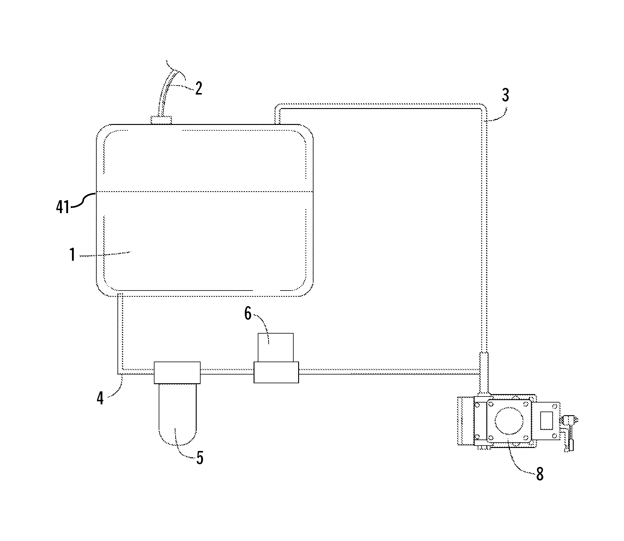
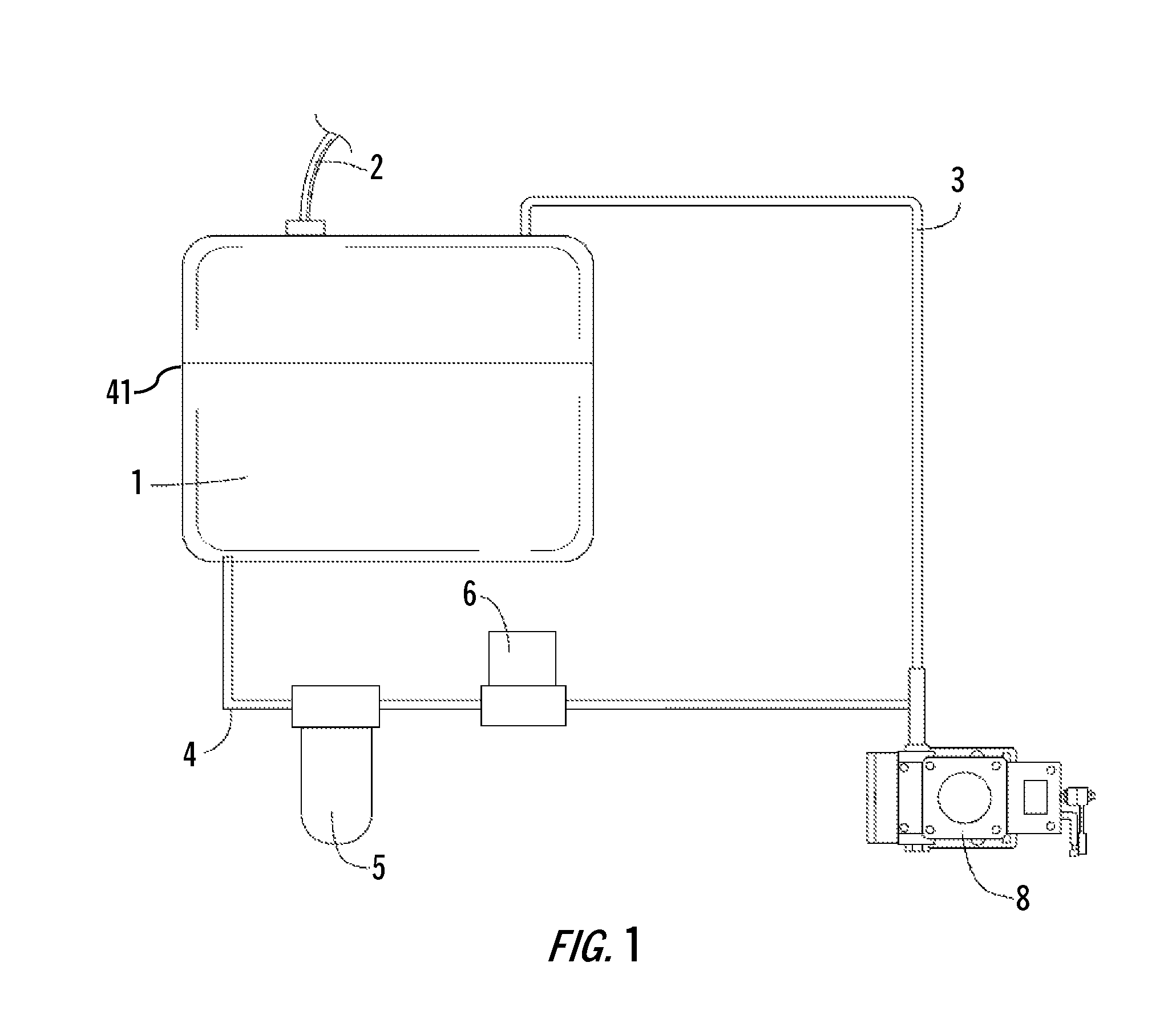
[0027]FIG. 1 shows a generic vehicle fuel storage and distribution system, including a fuel tank 1, a fill tube 2, a fuel line 4, a fuel filter 5, a fuel pump 6, and an injector 8. Fuel that is not used by the injector 8 is returned to the fuel tank 1 via the return fuel line 3. The fuel tank 1 has a shell 41.

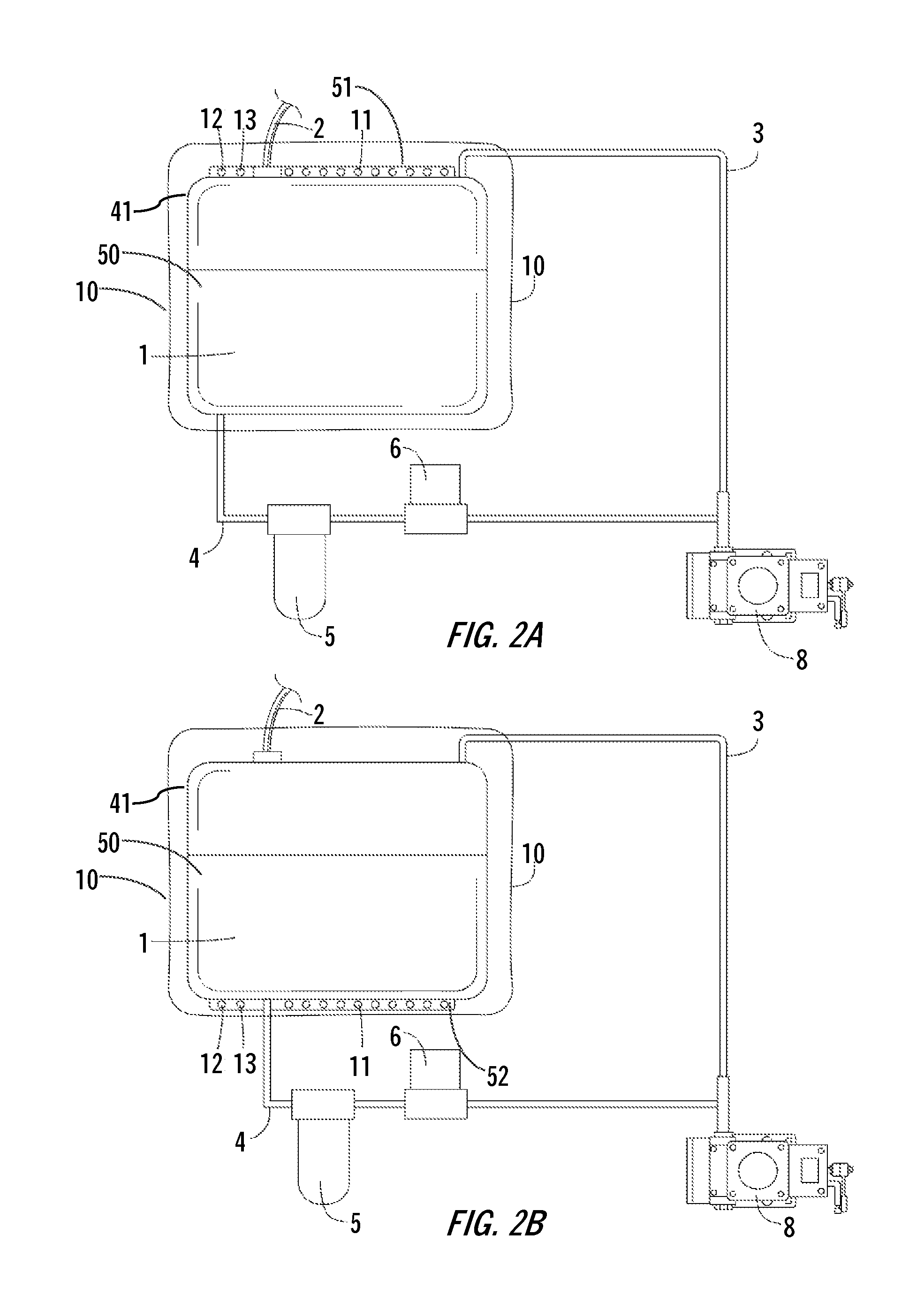
[0028]FIG. 2A shows a generic vehicle fuel storage and distribution system with the present invention included. The standard elements from FIG. 1 are present: a fuel tank 1, fuel tank shell 41, a fill tube 2, a fuel line 4, a fuel filter 5, a fuel pump 6, an injector 8, and a return fuel line 3. The fuel tank 1 has a volume of bulk fuel 50 contained within the fuel shell 41. In addition, on the top of the tank, there...


PUM


Abstract

A method and system for cooling the fuel contained in the fuel storage tank of motor vehicles using internal combustion engines. The method and system uses tubing in intimate contact with the exterior of the fuel tank to cool the fuel tank. The method and system may optionally employ an insulating wrap or shell to improve thermal efficiency.

Description

FIELD OF INVENTION[0001]This invention relates to internal combustion engines. Specifically, this invention relates to cooling the fuel storage tank for an internal combustion engine.BACKGROUND OF INVENTION[0002]The internal combustion engine (ICE) is a self-contained powerplant in which a vapor consisting of a fossil fuel (gasoline or diesel) and oxygen is ignited in a sealed combustion chamber. The ICE has revolutionized society, leading the unprecedented industrialization of the western world in the 20th century. Now, ICEs are ubiquitous, being the favored power source for automobiles, light trucks, and heavy trucks.[0003]Between now and the year 2020, it is estimated that the total worldwide car parc (total registered light vehicles) will grow from approximately 620 million units to almost 1 billion units. During that same time, the annual worldwide new vehicles sales will grow from approximately 80 million to 115 million units per year. This explosion in vehicle ownership will ...

Claims


Application Information

Patent Timeline
Patent Type & Authority Patents(United States)
IPC IPC(8): F02M37/04B60H1/00B60K15/03
CPCB60H1/00271B60K15/03B60K15/03177B60K2015/03414B60K2015/03493
Inventor BILLS, ANTWANETTEBILLS, ANTHONY
Owner BILLS ANTWANETTE
Why Eureka
Try Eureka