
Thermally efficient gas turbine engine for an aircraft

hermal efficiency technology, applied in the direction of machines/engines, stators, efficient propulsion technologies, etc., can solve the problems of increasing weight, complexity, cost, and incorporating a heat exchanger into a gas turbine engine, and achieves the effects of reducing installation, recurrent and direct maintenance costs, and increasing thermal efficiency

Active Publication Date: 2019-12-03
AIRBUS OPERATIONS SL
View PDF11 Cites 0 Cited by
  • Summary
  • Abstract
  • Description
  • Claims
  • Application Information

AI Technical Summary

Benefits of technology

This patent is about a gas turbine engine that can perform heat exchange without needing a separate device. This results in a more efficient engine and reduces the need for maintenance. The engine also uses common components, making it easier to install and modify. Overall, the invention improves efficiency and reduces costs without requiring a dedicated device.

Problems solved by technology

However, incorporating a heat exchanger in a gas turbine engine carries some disadvantages, such as an increase in weight, complexity, and cost.

Method used


Image

  • Thermally efficient gas turbine engine for an aircraft
  • Thermally efficient gas turbine engine for an aircraft
  • Thermally efficient gas turbine engine for an aircraft

Examples


Embodiment Construction

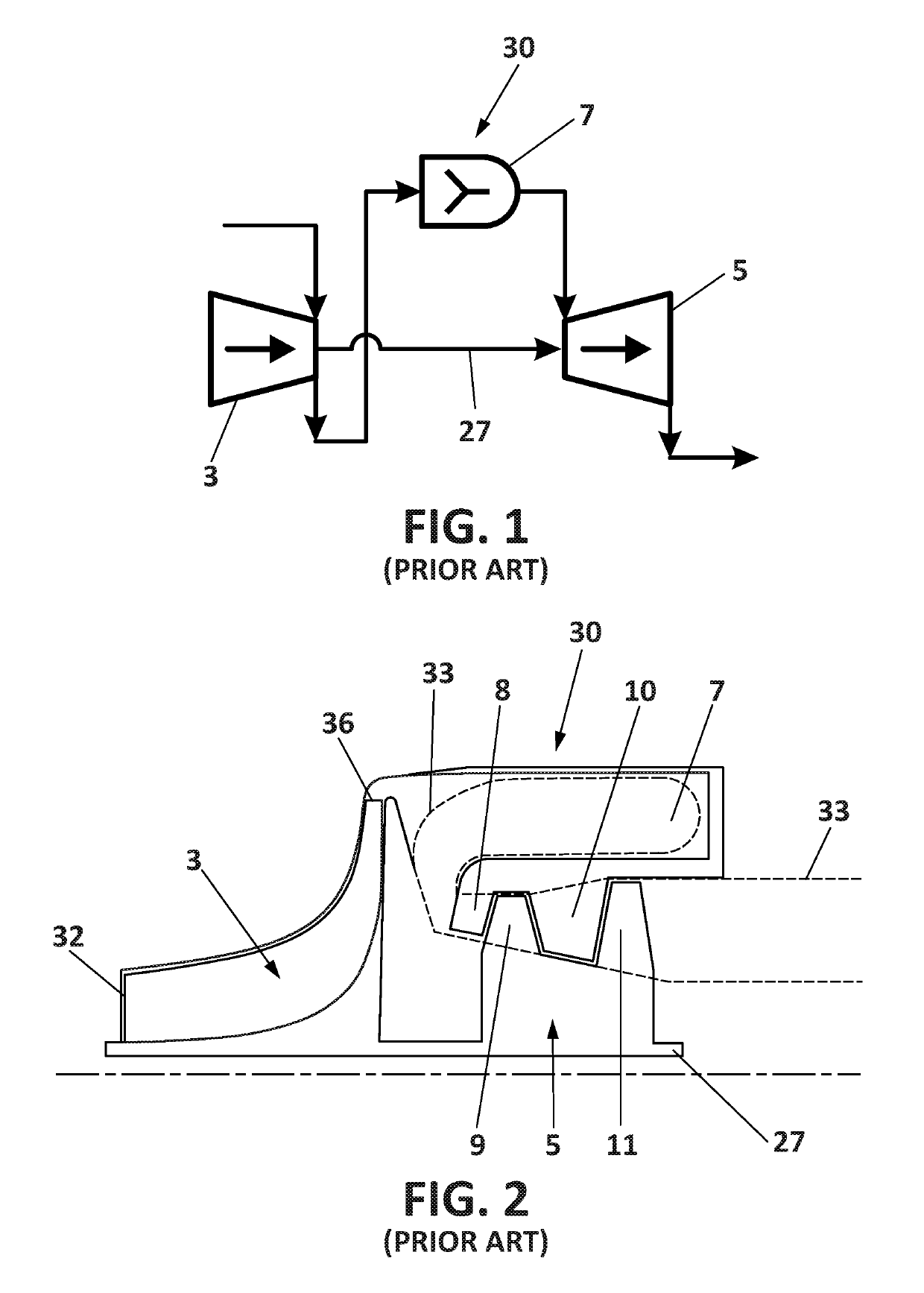
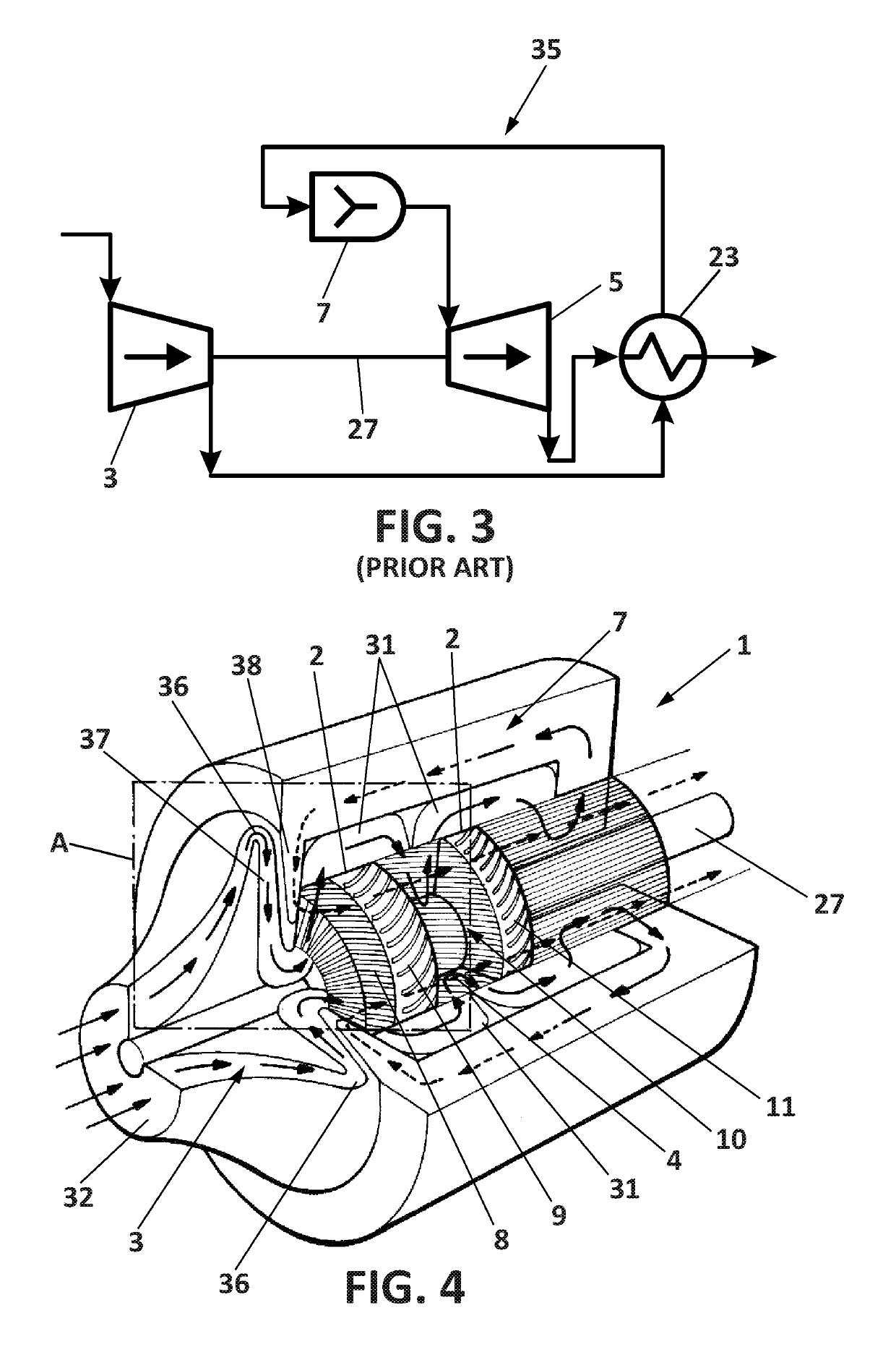
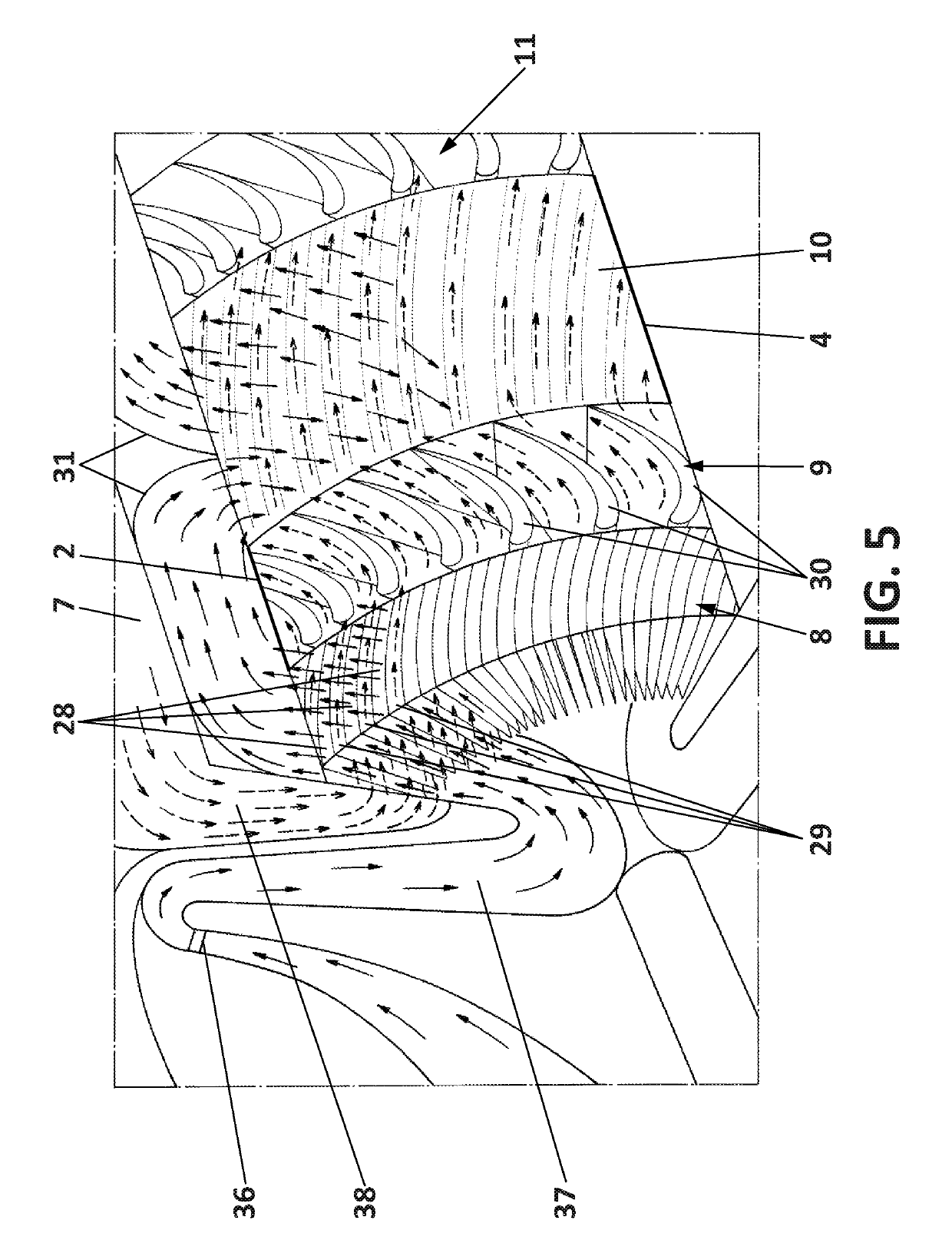
[0035]FIG. 4 shows a schematic perspective view of a gas turbine engine 1 for an aircraft. The engine 1 comprises a compressor 3 for increasing pressure and temperature of ambient air to obtain compressed air, a combustion chamber 7 for further increasing the temperature of the compressed air by burning it with fuel, and a turbine 5 disposed downstream of the combustion chamber 7 and comprising radially outer 2 and inner 4 walls, at least one stator 8, 10, and at least one rotor 9, 11.

[0036]The outer wall 2 and the inner wall 4 are circumferentially spaced around the engine. The outer wall 2 of the turbine having a radial step, and the inner wall 4 overlapping said radial step.

[0037]Each stator 8, 10 and each rotor 9, 11 is formed by a plurality of blades, wherein each blade has two opposing surfaces. A fluid channel is formed between each two consecutive blades.

[0038]According to an embodiment of the invention, the stator channels are formed by a first group 28 and a second group 2...


PUM


Abstract

A gas turbine engine for an aircraft includes a compressor, a combustion chamber, and a turbine having at least one stator, and at least one rotor. Each stator and rotor is formed by a plurality of blades, a fluid channel is formed between two consecutive blades, and each blade has two opposing surfaces. The compressor is in fluid communication with a first group of stator channels, and the combustion chamber is in fluid communication with a second group of stator channels, such that heat exchange can be performed through two opposing surfaces of at least one stator blade. The outer and the inner walls define a duct for the passage of the heated fluid through the rotor blades, and the outer wall is also arranged for directing the compressed air towards the combustion chamber.

Description

FIELD OF THE INVENTION[0001]The present invention refers to a design of a gas turbine engine for being used in an aircraft, as a main engine or / and as an auxiliary power unit.[0002]An aspect of the invention may provide a more thermally efficient gas turbine engine, without increasing the weight and cost of conventional gas turbine engines, and without requiring dedicated devices for achieving such efficiency.[0003]Another aspect of the present invention may provide a gas turbine engine capable of minimizing pressure losses, generally caused by dedicated devices traditionally used for improving the thermal efficiency of gas turbine engines.[0004]Another aspect of the present invention may provide a simplified gas turbine engine that allows saving weight, cost and space when installed in the aircraft.BACKGROUND OF THE INVENTION[0005]Gas turbine engines are well-known for providing propulsion and power production. Conventionally, a gas turbine engine consists of an upstream rotating c...

Claims


Application Information

Patent Timeline
Patent Type & Authority Patents(United States)
IPC IPC(8): F01D1/12F02C9/18F02C3/04F01D15/12F01D17/10F01D15/10F01D9/04B64D41/00F01D5/02F02C3/14F02C7/10B64D27/10F02C7/08
CPCF01D15/12F02C3/145F02C3/04F02C7/08F01D9/041B64D27/10F01D17/105F02C7/10B64D41/00F01D5/02F01D1/12F01D15/10F02C9/18B64D2041/002Y02T50/671F05D2240/35F05D2240/60F05D2220/323F05D2220/50Y02T50/60
Inventor GARDE LA CASA, ALEXANDRE
Owner AIRBUS OPERATIONS SL
Learn More