
Dual-Band Series-Aligned Complementary Double-V Antenna, Method of Manufacture and Kits Therefor

a technology of complementary double-v antennas and series alignment, applied in the direction of antennas, radiating elements, protective materials, etc., can solve the problems of increased interference, poor efficiency, and difficulty in optimizing a single antenna for both frequency modes

Active Publication Date: 2014-02-13
TAOGLAS GROUP HLDG
View PDF5 Cites 1 Cited by
  • Summary
  • Abstract
  • Description
  • Claims
  • Application Information

AI Technical Summary

Benefits of technology

This patent is about planar antennas and their manufacturing process. The technical effects of this patent include the design of a planar antenna with a ground section and a radiation section that fit together like a lock and key, and the use of a conductive layer that has a U-shaped opening and an elongated radiation section. The antenna can also have an insulation layer with an aperture exposing a portion of the ground or radiation section. The patent also describes the use of a flexible cable and a planar antenna mounting material for connecting the antenna to a target device. The patent also mentions the manufacturing process of patterning a substrate with a conductive layer and the materials that can be used for the conductive layer.

Problems solved by technology

For the latest dual-band Wi-Fi antennas, increased interference is problematic in the 2.4 and 5 GHz frequency modes.
It has also been difficult for a single antenna to be optimized for both frequency modes.
Currently antennas are either optimized for one frequency or another or performance in both modes results in poor efficiency.

Method used


Image

  • Dual-Band Series-Aligned Complementary Double-V Antenna, Method of Manufacture and Kits Therefor
  • Dual-Band Series-Aligned Complementary Double-V Antenna, Method of Manufacture and Kits Therefor
  • Dual-Band Series-Aligned Complementary Double-V Antenna, Method of Manufacture and Kits Therefor

Examples


examples

[0042]Experimental antennas according to this disclosure have been constructed and tested. FIG. 5 shows an actual measured gain characteristic of an embodiment of an antenna 100 using a lower band and an upper band operating in the 2.4 GHz Wi-Fi mode, and FIG. 6 shows a gain characteristic of the same antenna operating in the 5 GHz Wi-Fi mode with a power range measurement from −16 dMB (violet) to 4 dMb (red) where dBm is a power level in decibels relative to 1 Watt. Antenna 100 was tested in a lab with an antenna 100 orientation as described in FIG. 4. TABLE 1 lists the performance specification of the antenna measured in FIGS. 5 and 6.

TABLE 1SPECIFICATION OF AN EXPERIMENTAL ANTENNA2.4 GHz5 GHzOtherStandardBluetoothWi-FiWi-Fi5 GHzBand (MHz)2,401-2,4802,400-2,5005,725-5,8254,900-5,900Peak Gain2222(dBi)Average Gain−2~−3−2~−4Efficiency (%)50-60%40-55%

[0043]As discussed above, the gain of the antenna is closely linked to the surface area or volume of the antenna. Moreover, the antenna ...


PUM


Abstract

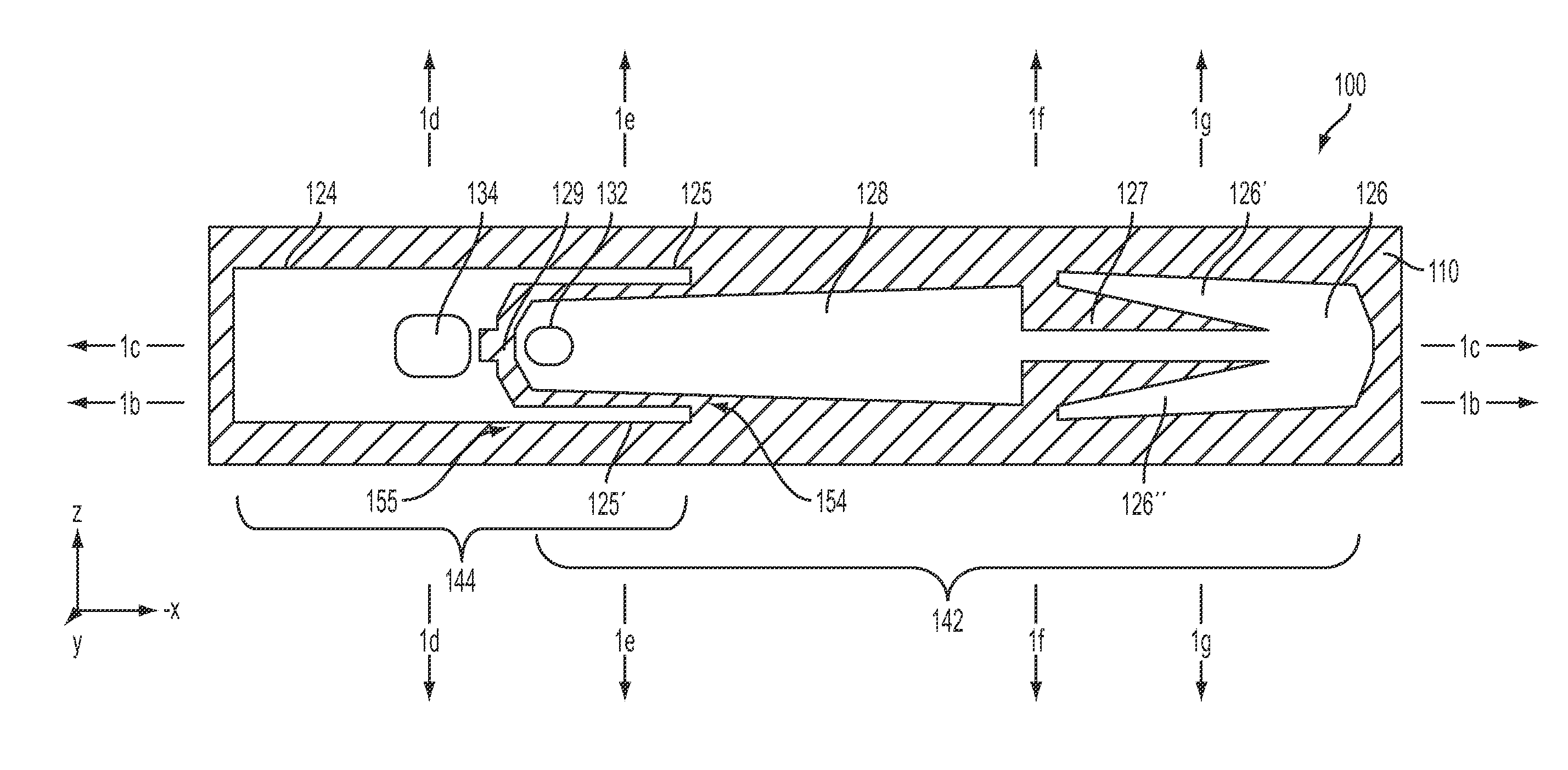
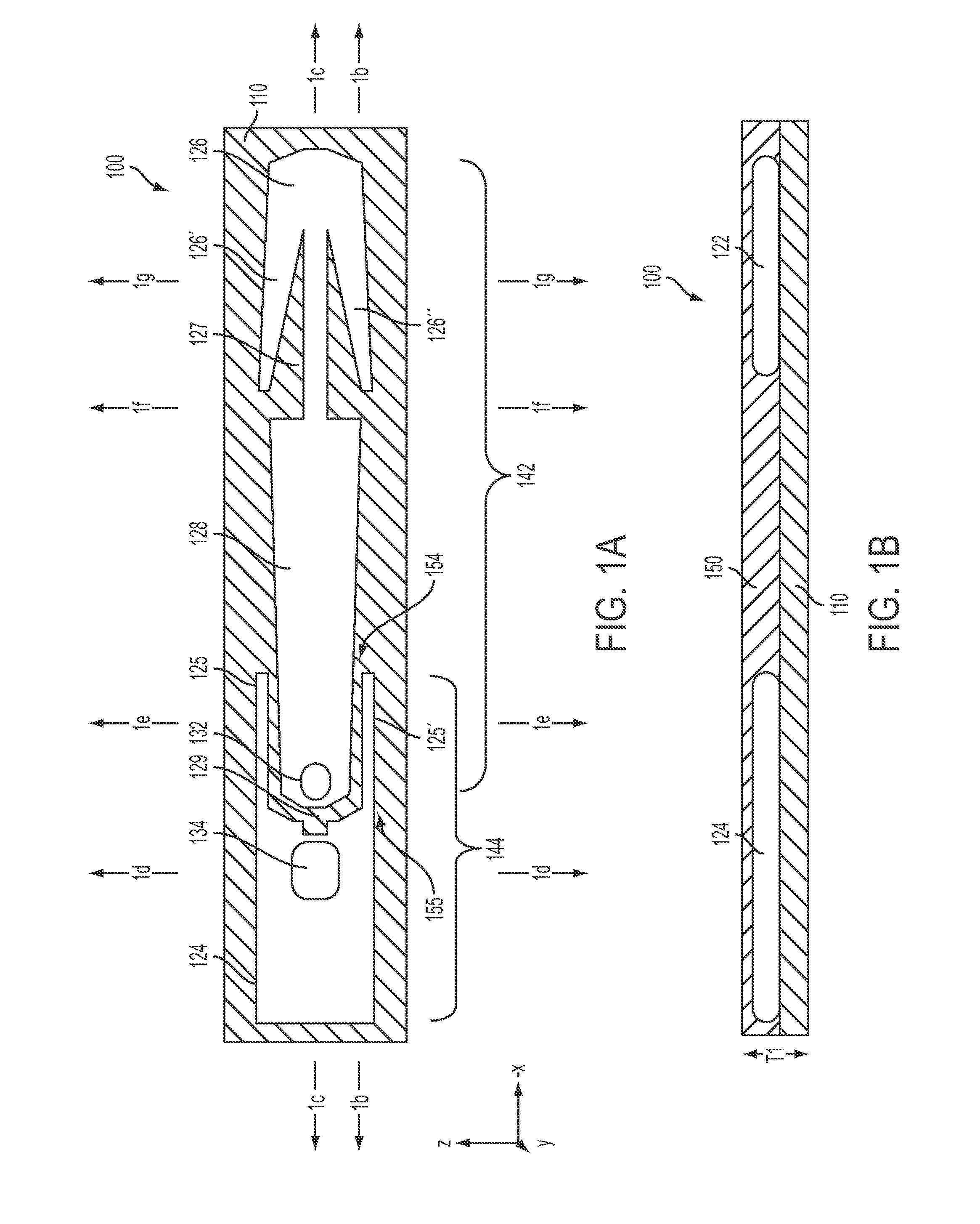
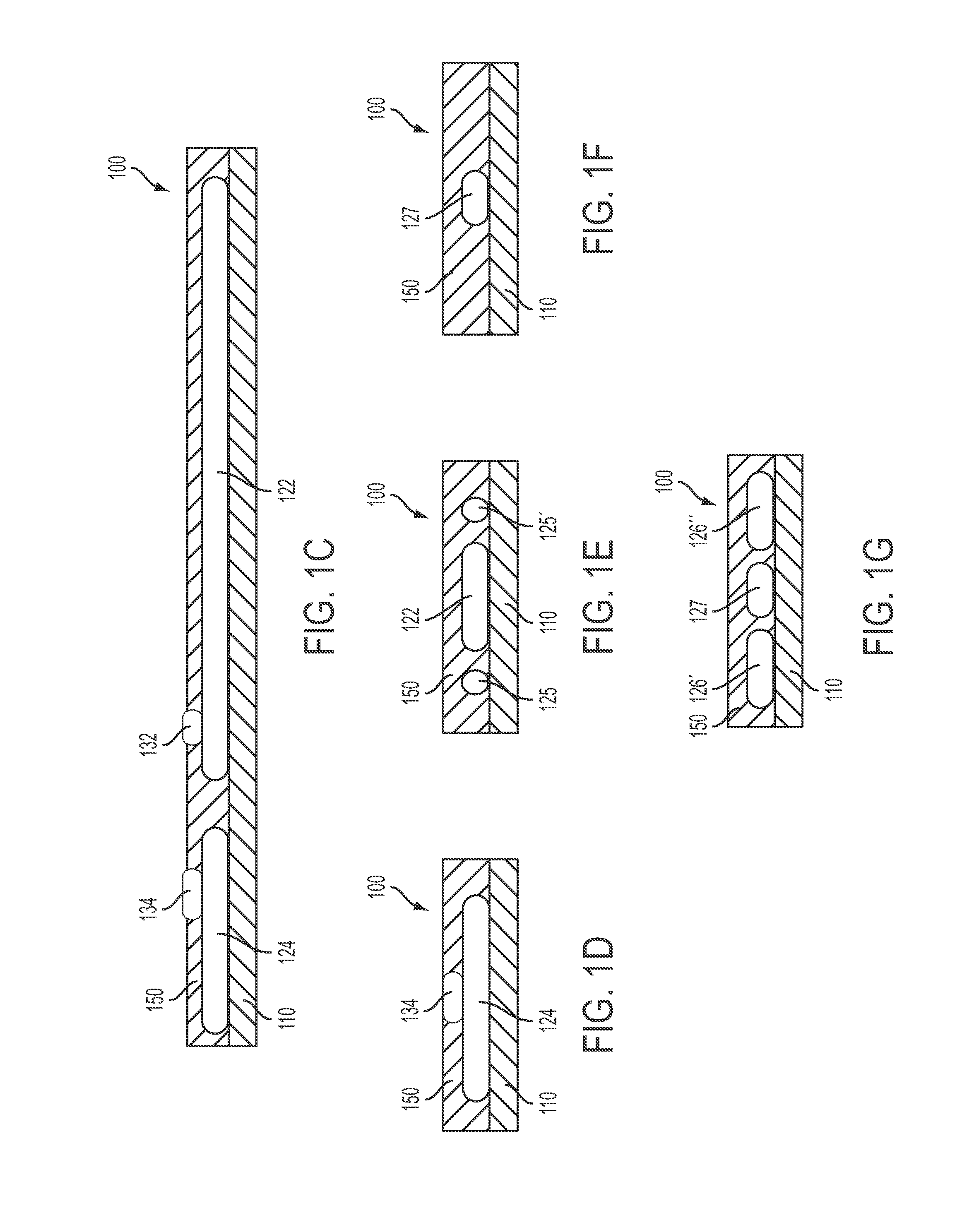
A planar monopole antenna for dual-band Wi-Fi application is disclosed. The antenna has a ground copper and a radiation copper. The radiation copper is adhered to a substrate and has an arrowhead-shaped pattern connected to a long-wide pattern. The arrowhead and long-wide patterns are aligned along the longitudinal direction of the antenna. The ground copper is adhered to the substrate and has a rectangularly-shaped pattern with an opening at one end thereof for the reception of the base of the long-wide pattern of the radiation copper in the longitudinal direction. Reception of the radiation copper into the opening of the ground copper forms an U-shaped separation that is approximately 0.6 mm wide. The antenna has a gross span of approximately 45 mm and a width of approximately 7 mm.

Description

CROSS-REFERENCE[0001]This application claims the benefit of U.S. Provisional Application No. 61 / 440,711, filed Feb. 8, 2011, which application is incorporated herein by reference.BACKGROUND OF THE INVENTIONField of the Invention[0002]The present invention relates in general to an antenna and, in particular, to a planar antenna. More particularly, the present invention relates to a coupled dual-band dipole antenna having an interference-cancellation gap for wireless applications such as Wi-Fi™, wireless HDTV, Bluetooth, Public Safety, RFID, WIMAX, tolling, remote control and unlicensed band wireless applications. The invention is suitable for use in any wireless application, including, but not limited to those which use 2400-2500 MHz and 4900-6000 MHz bands.BACKGROUND OF THE INVENTION[0003]In recent years there has been a tremendous increase in the use of wireless devices. The increased use has filled all or nearly all existing frequency bands. As a result, new wireless frequency sta...

Claims


Application Information

Patent Timeline
IPC IPC(8): H01Q5/01H01Q5/10H01Q5/364
CPCH01Q5/01H01Q1/2291H01Q1/40H01Q9/40H01Q5/364H01Q5/10H01Q5/30H01Q1/48
Inventor FLORES-CUADRAS, JAVIER RUBEN
Owner TAOGLAS GROUP HLDG
Learn More