Antenna device, wireless communication device, and method of manufacturing antenna device

a technology of wireless communication and antenna device, which is applied in the direction of loop antenna, waveguide type device, loop antenna, etc., can solve the problems of insufficient sintered magnetic substance, inability to set the firing temperature to a high temperature of 900° c. or higher, etc., to achieve the effect of improving efficiency percentage, low loss characteristic, and increasing the maximum communicable distan

Active Publication Date: 2014-02-13
MURATA MFG CO LTD
View PDF5 Cites 46 Cited by
  • Summary
  • Abstract
  • Description
  • Claims
  • Application Information

AI Technical Summary

Benefits of technology

[0028]In addition, with the wireless communication device according to the various preferred embodiments of the present invention, a low loss characteristic and an increase in maximum communicable distance is achieved.
[0029]Moreover, wi

Problems solved by technology

While the sintering temperature of the magnetic substance is not less than 1000° C., however, the firing temperature of silver is approximately 800° C. to 900° C., so that the firing temperature cannot be set to a high temperature of 900° C. or higher.
As a re

Method used


Image

  • Antenna device, wireless communication device, and method of manufacturing antenna device
  • Antenna device, wireless communication device, and method of manufacturing antenna device
  • Antenna device, wireless communication device, and method of manufacturing antenna device

Examples


first preferred embodiment

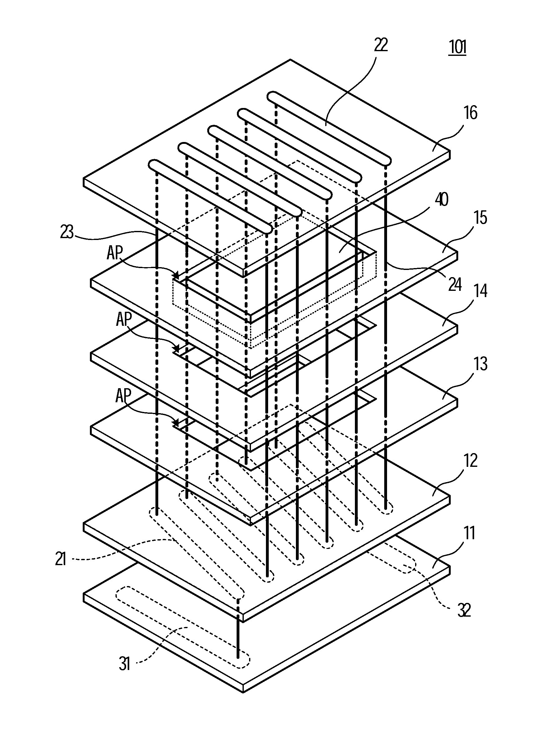
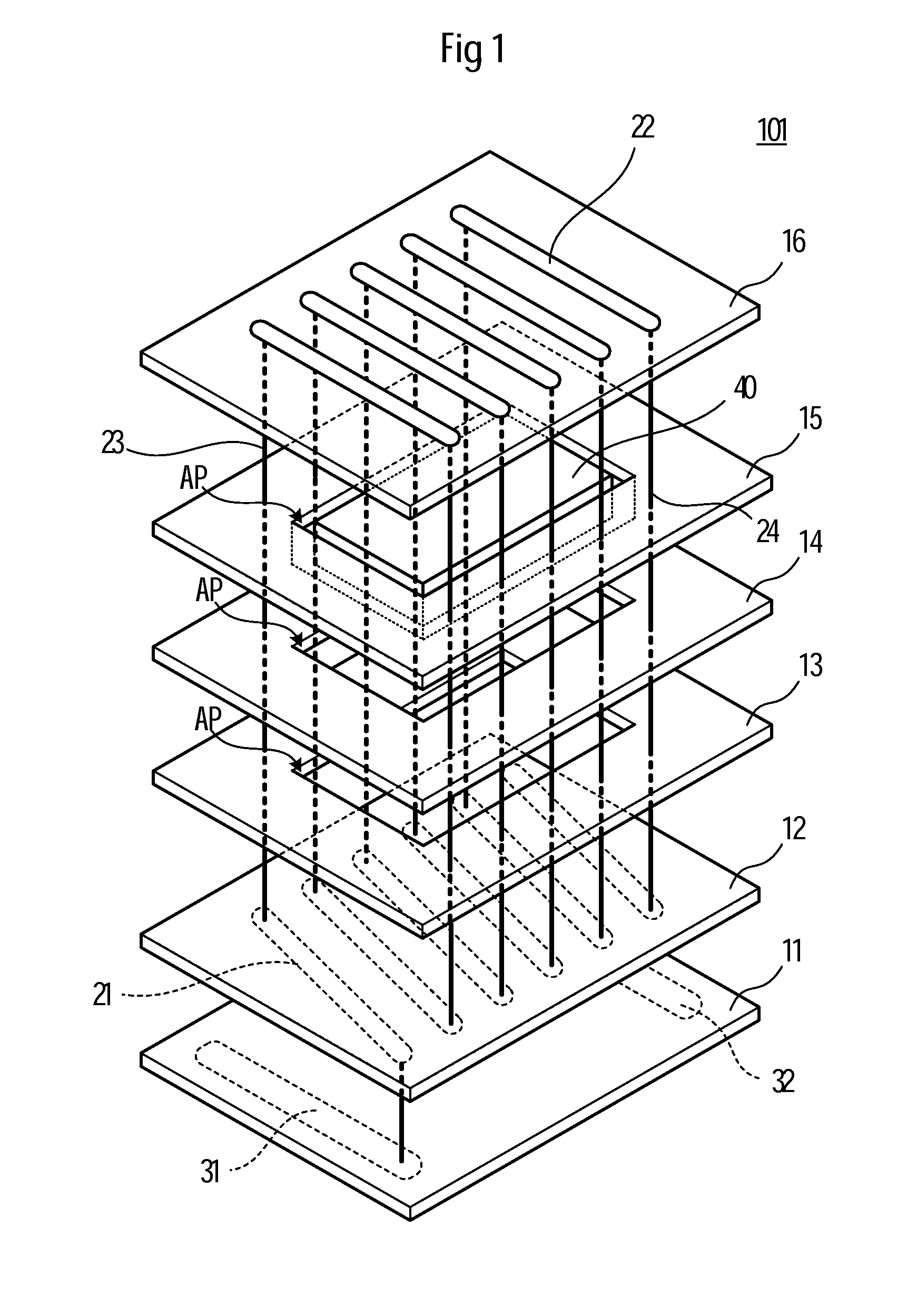
[0066]FIG. 1 is an exploded perspective view of an antenna device 101 according to a first preferred embodiment of the present invention. FIG. 2 is a perspective view of the antenna device 101. FIG. 3A is an exploded cross-sectional view of a main portion of the antenna device 101, and FIG. 3B is a cross-sectional view of the main portion of the antenna device 101.

[0067]The antenna device 101 includes a resin multilayer substrate 10 in which a plurality of resin sheets 11 to 16 are laminated to one another, and a coil conductor located on the resin multilayer substrate 10. The resin sheet 12 includes a plurality of linear portions 21 of the coil conductor on the lower surface thereof. The resin sheet 16 includes a plurality of linear portions 22 of the coil conductor located on the upper surface thereof. The resin sheets 12 to 16 include a plurality of via conductors (interlayer connection conductors) 23 and 24 of the coil conductor. These via conductors 23 connect a first end of th...

second preferred embodiment

[0084]In a second preferred embodiment, a description is given of some configuration examples of a layered structure including a resin sheet and a magnetic substance core.

[0085]FIG. 7A is an exploded cross-sectional view showing a main portion of an antenna device according to the second preferred embodiment of the present invention, and FIG. 7B is a cross-sectional view.

[0086]In this example, the position in which the linear portions 21 and 22 of a coil conductor are located is such that the linear portions 21 and 22 of the coil conductor contact the magnetic substance core 40. According to this structure, the inductance obtained per overall line length of the coil conductor is large, so that conductor loss can be reduced and the Q value can be increased.

[0087]FIG. 8A is an exploded cross-sectional view showing a main portion of an antenna device according to the second preferred embodiment of the present invention, and FIG. 8B is a cross-sectional view. In this example, the gap be...

third preferred embodiment

[0098]FIG. 13 is an exploded perspective view of an antenna device 103 according to a third preferred embodiment of the present invention while FIG. 14 is a perspective view of the antenna device 103.

[0099]The antenna device 103 includes a resin multilayer substrate 10 in which a plurality of resin sheets 11 to 17 are laminated to one another, and a coil conductor located on the resin multilayer substrate 10. The resin sheets 12 to 16 each include an aperture AP formed therein and define a cavity CA by laminating the apertures. The cavity CA includes a magnetic substance core 40 that is embedded therein. The resin sheets 12 to 16 also include a coil conductor 20 that is arranged so as to extend around on the surface of the resin sheets 12 to 16, and respective coil conductors 20 of the resin sheets are connected to each other through a via conductor formed in the resin sheets 13 to 16. In addition, one end of the coil conductor 20 located in the resin sheet 16 is connected to the te...


PUM

PropertyMeasurementUnit
Shapeaaaaaaaaaa
Magnetismaaaaaaaaaa
Dielectric constantaaaaaaaaaa

Abstract

In an antenna device, first linear portions of a coil conductor are located on a lower surface of a first resin sheet. Second linear portions of the coil conductor are located on an upper surface of a second resin sheet. Via conductors of the coil conductor are formed in the first and second resin sheets and intermediate resin sheets located between the first and second resin sheets. The via conductors connect a first end and a second end of the first linear portions and a first end and a second end of the second linear portions, respectively. The first and second linear portions and the via conductors define the coil conductor. Each of the intermediate resin sheets includes an aperture in the center portion thereof. The lamination of the apertures defines a cavity in which a magnetic substance core is embedded. The coil conductor is wound around a periphery of the cavity.

Description

[0001]This non-provisional application claims priority under 35 U.S.C. §119(a) to Patent Application No. 2012-176950 filed in Japan on Aug. 9, 2012, and Patent Application No. 2013-008873 filed in Japan on Jan. 22, 2013, the entire contents of which are hereby incorporated by reference.BACKGROUND OF THE INVENTION[0002]1. Field of the Invention[0003]The present invention relates to an antenna device that includes a magnetic substance and a coil conductor, a wireless communication device that includes the antenna device, and a method of manufacturing the antenna device.[0004]2. Description of the Related Art[0005]Japanese Patent No. 4821965 discloses an antenna device having a layered structure in order to realize in a small area an antenna equipped with a magnetic substance, the antenna device performing short-range wireless communication such as Near Field Communication (NFC). By using such a layered structure, the aperture diameter of an antenna coil can be changed only by varying ...

Claims


Application Information

Patent Timeline
IPC IPC(8): H01Q7/06
CPCH01Q7/06H01Q1/2225H01Q1/243H01Q7/08Y10T29/49016H01L2224/16227H01L2924/19105
Inventor GOUCHI, NAOKIIKEMOTO, NOBUOYOSUI, KUNIAKITAMURA, WATARU
Owner MURATA MFG CO LTD
Why Eureka
Try Eureka