Blind i/q mismatch compensation with receiver non-linearity

a receiver non-linearity and blind technology, applied in the field of electronic circuits, can solve problems such as i/q mismatch, i/q mismatch, and extraneous lo energy components in the image spectrum, and achieve the effects of reducing dynamic range, preventing clipping, and sufficient dynamic rang

Active Publication Date: 2014-02-13
TEXAS INSTR INC
View PDF4 Cites 11 Cited by
  • Summary
  • Abstract
  • Description
  • Claims
  • Application Information

AI Technical Summary

Benefits of technology

[0018]ADC hardware with sufficient dynamic range to prevent clipping in a high dynamic range signal environment may be too expensive to match the design goals for a particular receiver type. Embodiments herein include clipping functions in the I and Q arms. The clipping functions perform additional clipping operations on data values in the non-dominant arm in order to balance clipping artifacts between the two arms. Balanced clipping and the balancing of other non-linearities in the I arm and Q arm contribute to matching statistical data distribution functions in the I and Q arms. Aligned data distribution functions associated with the receiver arms contribute to accurate gain & phase imbalance estimates. These embodiments and methods enable the use of lower-cost ADCs with correspondingly lower dynamic range. They may be particularly useful in RF receivers designed to process signals of high Peak-to-Aveare ratio (PAR) such as WLAN receivers and receivers processing highly Gaussian noise content such as GPS receivers
[0023]The invented structures and methods provide for gain, clipping, and phase compensation in the presence of I / Q mismatch exacerbated by differential clipping in low resolution I and Q ADCs. Improved image rejection performance may enhance receiver operation.

Problems solved by technology

In actual practice, the I and Q arm LO signals often vary somewhat in magnitude and drift in phase away from perfect quadrature, creating a problem referred to as I / Q mismatch.
Other factors such as non-ideal low-pass filter characteristics may also contribute to I / Q mismatch.
I / Q mismatch results in extraneous LO energy components in the image spectrum and the subsequent down-conversion of image spectrum interference.
Said differently, I / Q mismatch results in decreased image rejection performance and lower SNRs.

Method used


Image

  • Blind i/q mismatch compensation with receiver non-linearity
  • Blind i/q mismatch compensation with receiver non-linearity
  • Blind i/q mismatch compensation with receiver non-linearity

Examples


Embodiment Construction

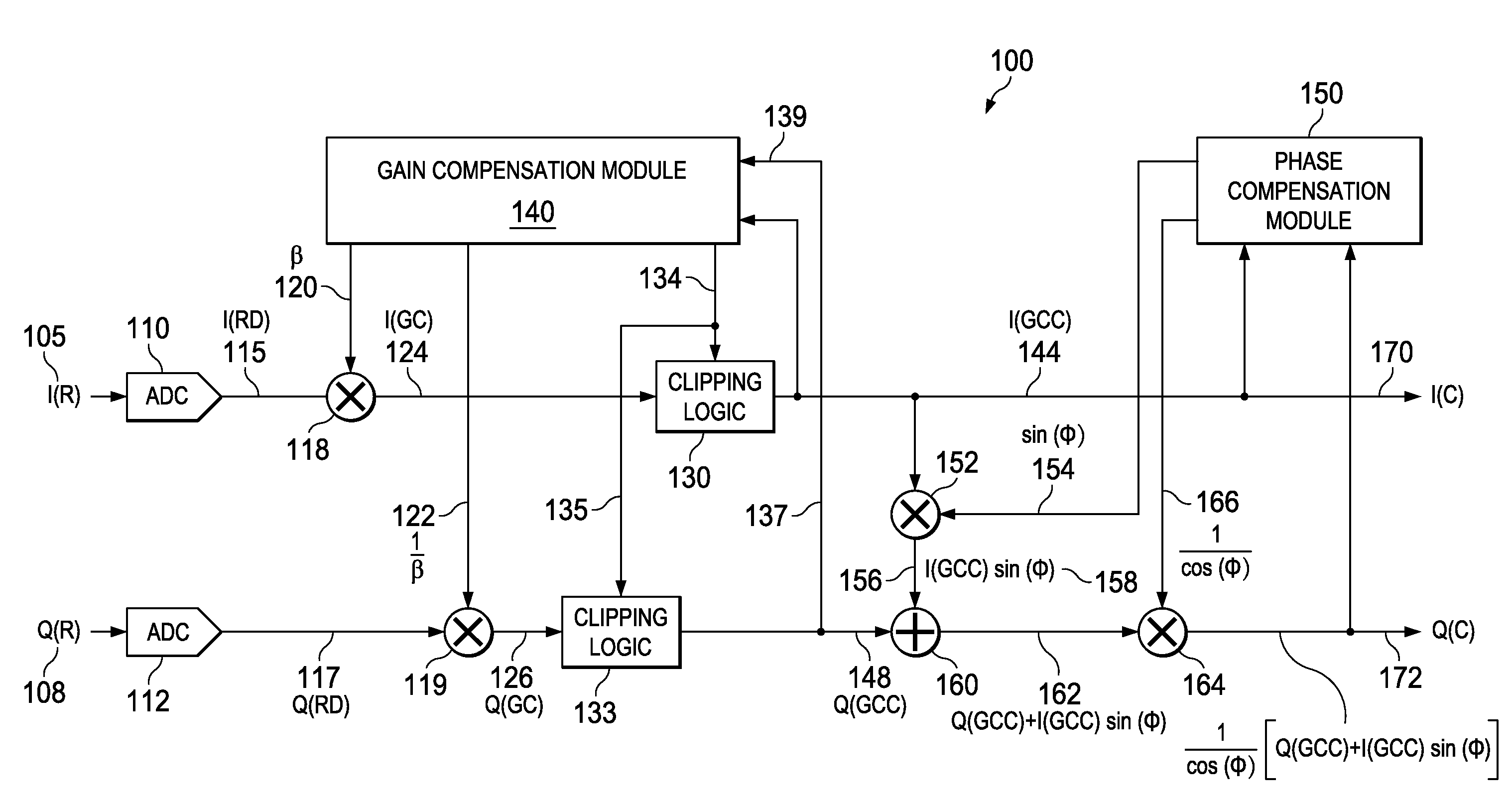
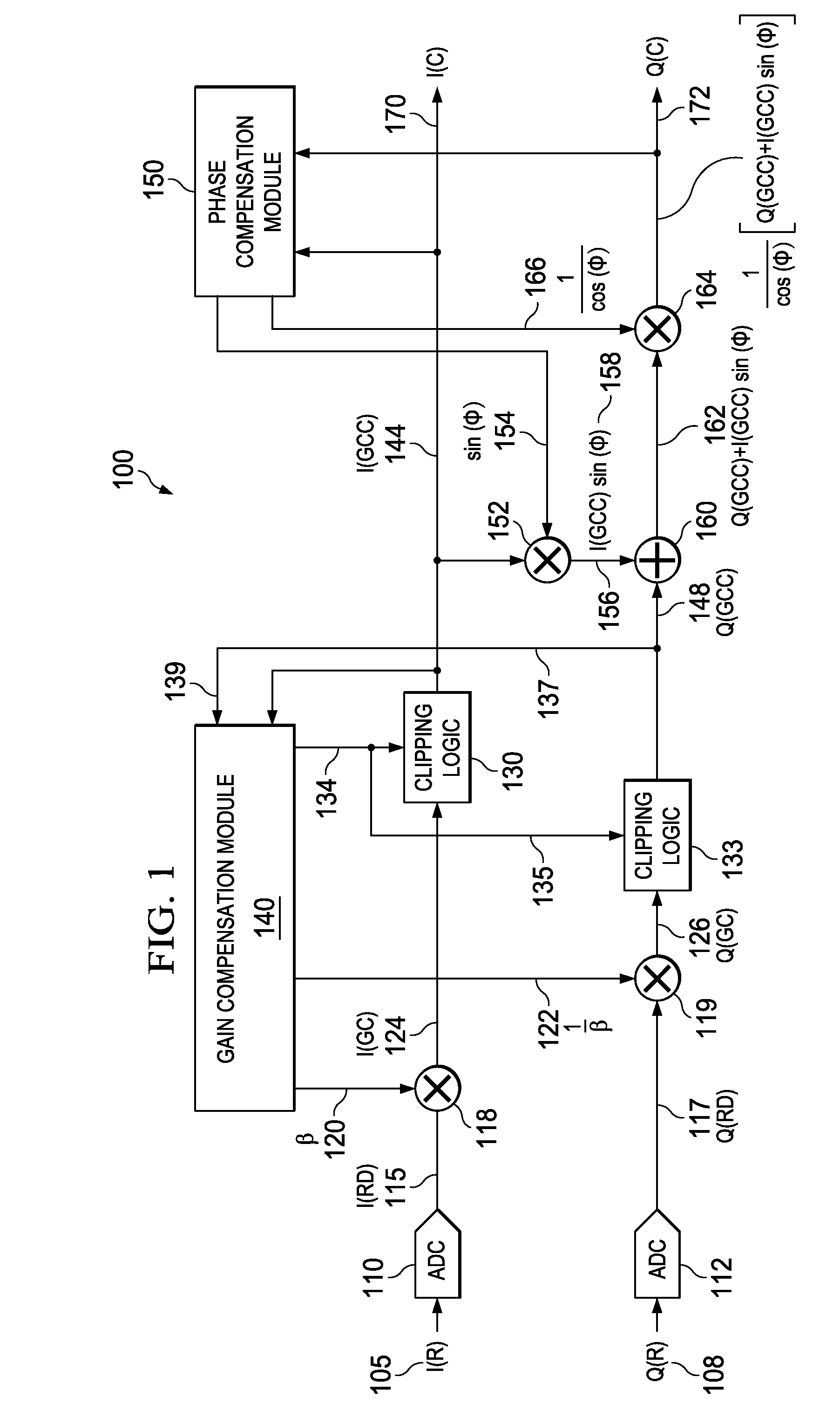
[0024]FIG. 1 is a diagram of a gain and phase compensation network 100 according to various example embodiments of the invention. Down-converted and filtered analog signals I(R) 105 and Q(R) 108 are received at ADCs 110 and 112, respectively. The ADC's 110 and 112 convert the analog signals I(R) 105 and Q(R) 108 to digitally sampled data streams I(RD) 115 and Q(RD) 117, respectively.

[0025]The compensation network 100 includes an I-arm multiplier 118 and a Q-arm multiplier 119 communicatively coupled to the ADCs 110 and 112, respectively. The I-arm multiplier 118, the Q-arm multiplier 119, or both, factor one or more sets of received data samples from the I-arm data stream I(RD) 115 and / or the Q-arm data stream Q(RD) 117. I-arm data samples, if factored, are factored by a gain compensation coefficient β appearing at a multiplier input 120. Q-arm data samples, if factored, are factored by a gain compensation coefficient 1 / β appearing at a clipping logic module input 122. Gain-compensa...


PUM


Abstract

Apparatus and methods disclosed herein perform gain, clipping, and phase compensation in the presence of I / Q mismatch in quadrature RF receivers. Gain and phase mismatch are exacerbated by differences in clipping between I & Q signals in low resolution ADCs. Signals in the stronger channel arm are clipped differentially more than weaker signals in the other channel arm. Embodiments herein perform clipping operations during iterations of gain mismatch calculations in order to balance clipping between the I and Q channel arms. Gain compensation coefficients are iteratively converged, clipping levels are established, and data flowing through the network is gain and clipping compensated. A compensation phase angle and phase compensation coefficients are then determined from gain and clipping compensated sample data. The resulting phase compensation coefficients are applied to the gain and clipping corrected receiver data to yield a gain, clipping, and phase compensated data stream.

Description

TECHNICAL FIELD[0001]Embodiments described herein relate to apparatus and methods associated with electronic circuits, including RF receiver gain and phase mismatch compensation processing.BACKGROUND INFORMATION[0002]Quadrature radio frequency (RF) signal transmission and reception exploits the concept that a single carrier wave may carry two independent data streams, provided that the data streams modulate the carrier in quadrature. For example, one of the data streams may modulate the carrier as a sine function and the other data stream may modulate the carrier as a cosine function. In any case, the two modulation streams must have a phase offset of 90° with respect to each other. The quadrature data streams are typically referred to as I data and Q data, representing an in-phase data stream and a data stream that is in quadrature with the in-phase data stream, that is, at a phase angle of 90° thereto.[0003]A quadrature RF receiver splits the received signal into two paths, referr...

Claims


Application Information

Patent Timeline
Patent Type & Authority Applications(United States)
IPC IPC(8): H04B17/00H04L27/08H04L27/00
CPCH04L27/3863H04B1/0039
Inventor RAGHU, GANESANBHUKANIA, BIJOYBALAKRISHNAN, JAIGANESH
Owner TEXAS INSTR INC
Why Eureka
Try Eureka