Method and apparatus for recognizing an intensity of an aerosol in a field of vision of a camera on a vehicle

a technology of aerosol intensity and field of vision, applied in the field of methods, can solve the problems of dangerous travel situations, inability to recognize meteorological phenomena, and inconvenient driver assistance systems, and achieve the effect of avoiding blinding the driver

Active Publication Date: 2014-02-13
ROBERT BOSCH GMBH
View PDF12 Cites 13 Cited by
  • Summary
  • Abstract
  • Description
  • Claims
  • Application Information

AI Technical Summary

Benefits of technology

[0029]Here, a modification can be understood as not merely the radiation of light itself, but rather also as a modification of parameters for controlling the light radiation, such as a modification of the switchover time between high beams and low beams, or a modification of the direction of a radiation of light given a system of floating headlamp range regulation. The modification of the light radiation thus relates to a general modification or parametrization in the controlling of the illumination of the vehicle by the headlamp system. Such a specific embodiment of the present invention offers the advantage of an immediate supporting of the driver given the presence of aerosol in the field of view of the vehicle camera, in which for example the direction of the light radiated by the headlamps is immediately further lowered in the direction of the roadway in order to avoid blinding the driver. If the driver knows that, starting from a particular intensity of the aerosol in the air in front of the vehicle, the driver assistance system will automatically engage and is capable of correspondingly adapting the light radiation, driving can still take place with an optimal illumination of the vehicle, even with low intensity of the aerosol in the field of view of the vehicle camera.
[0030]According to a further specific embodiment of the present invention, in the step of modification a modification of a light radiation parameter can be determined as a function of the time of the presence of the aerosol, in particular the presence of a specified minimum intensity of the aerosol. A light radiation parameter can be understood for example as a debounce time (i.e. a time until the beginning of an increasing of the illuminated range), a speed, or a curve by which the illuminated range is increased, an illumination height up to which the headlamps emanate maximum light, or a similar parameter that can be set by an illumination system of the vehicle. Such a specific embodiment of the present invention offers the advantage that a very flexible device is possible for regulating the illuminated range as a function of a time during which a particular determined intensity of an aerosol is present. For example, when traveling through a foggy stretch, it can be recognized that travel has to take place through a high density of fog, or a long stretch in fog having a particular minimum density, so that there is a high probability that, after a recognition that the intensity of the fog has fallen below a given level, travel through a fog bank will again take place after a short time. In this situation, it can be very helpful if, from a modification of the light radiation by the illumination device, waiting then takes place for a longer time span (i.e. a longer debounce time) to find out whether travel through another fog bank having the high intensity will in fact take place, so that this would again lead to a lowering of the beams, or a further modification of the light radiation to the preceding state of illumination.
[0031]In addition, it is advantageous if, according to a further specific embodiment of the present invention, in the step of modification a light distribution is modified given an activated light radiation monitoring as a function of the recognized intensity of the aerosol. Such a specific embodiment of the present invention enables a very flexible device for regulating the illumination range as a function of an intensity of the aerosol, such as fog. In this way, the illumination range can be set for example as a function of the actually recognized intensity of the aerosol.
[0032]According to a further specific embodiment of the present invention, in the step of modification a modification of a light radiation parameter for a light output by the headlamp system of the vehicle can be changed between different states of illumination. Such a specific embodiment of the present invention offers the advantage that for example a switching of the headlamp system into different states of illumination (e.g. low beams or high beams) is very easily possible. For example, from a set of predefined illumination states, that state of illumination can be selected that is appropriate for the particular situation at that moment. In addition, such a specific embodiment of the present invention offers the advantage that, for example when traveling through fog, when repeated patches of fog occur the changeover from low beams to high beams does not take place too quickly, so that the driver is then not irritated, due to the omission of such a rapid change.

Problems solved by technology

Conventional driver assistance systems often offer no recognition, or very inadequate recognition, of meteorological phenomena when underway in the vehicle, such as the occurrence of fog or smoke in front of the vehicle.
In particular at night or in conditions of darkness, when the headlamps are switched on during travel this can result in dangerous travel situations, for example if, when entering a fog bank, the illumination is set too high and the driver is thus blinded by the strong reflection of light from the aerosol droplets that form the fog.

Method used


Image

  • Method and apparatus for recognizing an intensity of an aerosol in a field of vision of a camera on a vehicle
  • Method and apparatus for recognizing an intensity of an aerosol in a field of vision of a camera on a vehicle
  • Method and apparatus for recognizing an intensity of an aerosol in a field of vision of a camera on a vehicle

Examples


Embodiment Construction

[0037]In the following description of preferred exemplary embodiments of the present invention, identical or similar reference characters are used for elements shown in the various Figures and having similar function, and a repeated description of these elements is omitted.

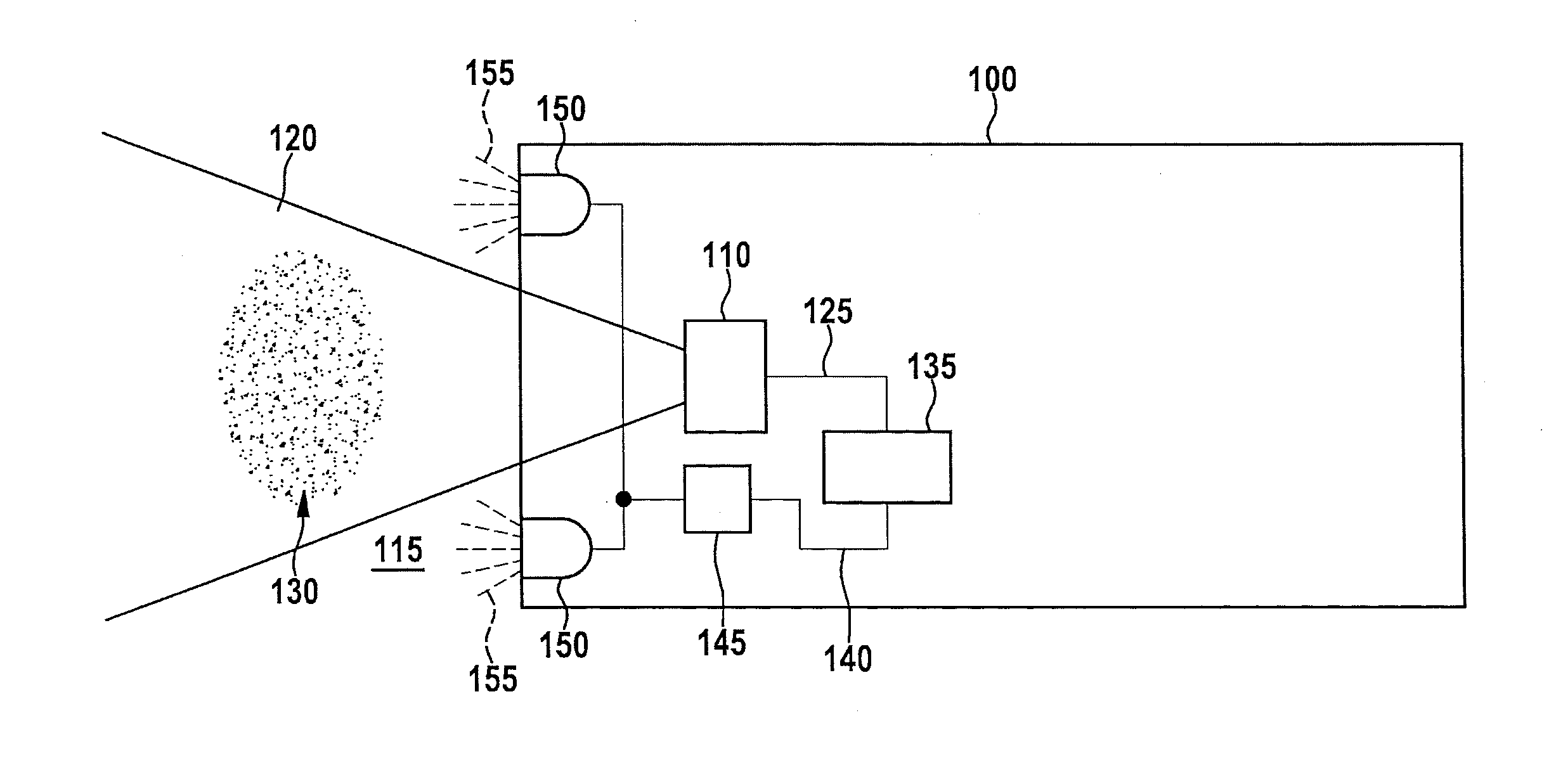
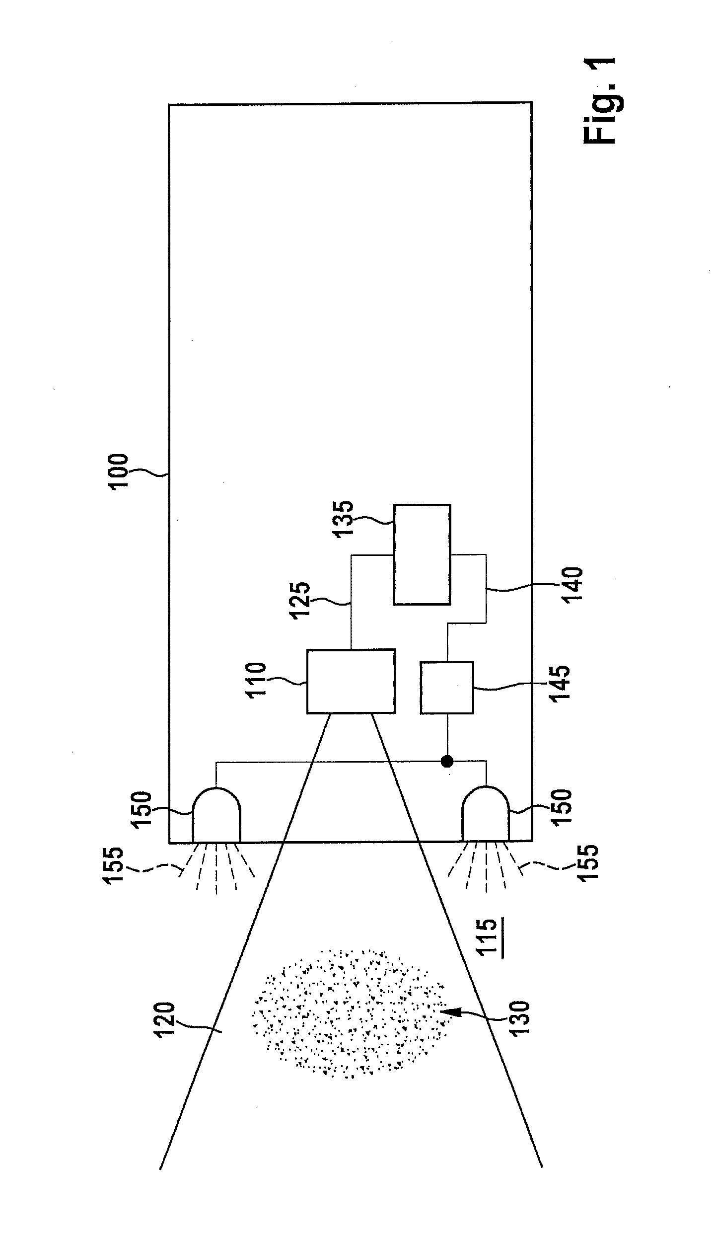
[0038]FIG. 1 shows a schematic diagram of a vehicle 100 containing an exemplary embodiment of the present invention. Vehicle 100 has a camera 110 for acquiring a surrounding environment 115 of the vehicle in a field of view 120 of camera 110, and for providing a corresponding camera image 125. Field of view 120 can in particular be a region in front of vehicle 100. An aerosol 130 whose intensity is to be recognized is contained in field of view 120. Camera image 125 is supplied to a device 135 that is fashioned for recognizing the intensity of the aerosol in the field of view of the camera of the vehicle. The precise functioning of device 135 is explained in more detail in the following. If it is now for example r...


PUM


Abstract

A method for recognizing an intensity of an aerosol in a field of view of a camera of a vehicle includes: reading in image information of an image of the camera, providing a color indicator value for at least one subsection of the image, the color indicator value representing a relation between (i) a first parameter representing a value obtained with application of a first color filter to the image information in the subsection, and (ii) a second parameter representing a value obtained without application of a color filter, or with application of a second color filter differing from the first color filter, and providing a gradient indicator value representing a brightness difference of a different image region of the image, an aerosol intensity value being determined using the color indicator and the gradient indicator values.

Description

BACKGROUND OF THE INVENTION[0001]1. Field of the Invention[0002]The present invention relates to a method for recognizing an intensity of an aerosol in a field of view of a camera of a vehicle, to a corresponding device, and to a corresponding computer program product.[0003]2. Description of the Related Art[0004]Conventional driver assistance systems often offer no recognition, or very inadequate recognition, of meteorological phenomena when underway in the vehicle, such as the occurrence of fog or smoke in front of the vehicle. In particular at night or in conditions of darkness, when the headlamps are switched on during travel this can result in dangerous travel situations, for example if, when entering a fog bank, the illumination is set too high and the driver is thus blinded by the strong reflection of light from the aerosol droplets that form the fog.[0005]DE 102010002488 (unpublished at the time of filing of the present application) proposes a spectroscopic method for recogni...

Claims


Application Information

Patent Timeline
Patent Type & Authority Applications(United States)
IPC IPC(8): B60Q1/08G06T7/00
CPCB60Q1/143B60Q1/20B60Q2300/312G06T2207/10016G06T2207/10024G06T2207/30192G06K9/00791G01N21/538B60Q1/085G06T7/00G06T7/44G06T7/90G06T2207/30252G06T7/40G06V20/56
Inventor EHLGEN, TOBIASVAN STAA, SEBASTIAN
Owner ROBERT BOSCH GMBH
Why Eureka
Try Eureka