Mold pump assembly

a technology of pump assembly and mold, which is applied in the direction of machines/engines, liquid fuel engines, and positive displacement liquid engines, etc., can solve the problems of control mechanism experiencing erratic control of the flow rate and pressure of molten metal, control of the flow of molten metal into the mold, and never found acceptance as a means to fill molten metal molds

Active Publication Date: 2014-02-13
PYROTECK INC
View PDF8 Cites 84 Cited by
  • Summary
  • Abstract
  • Description
  • Claims
  • Application Information

AI Technical Summary

Benefits of technology

[0006]In another embodiment of the present disclosure, a method of filling a mold with molten metal is provided. The method comprises rotating an impeller within a chamber. Molten metal is transferred through the impeller into the chamber. A predetermined portion of molten metal leaks through at least one bypass gap from the chamber to the base exterior. The leakage rate allows for precise tuning of a head pressure relative to a rotational speed of the impeller. An associated mold is filled with the molten metal and is controlled by a programmable control profile.
[0009]One aspect of the present disclosure is an assembly and method of use for a molten metal pump to fill complex molds such that the bypass gap allows for a more precise flow control.

Problems solved by technology

Although centrifugal pumps operate satisfactorily to pump molten metal, they have never found acceptance as a means to fill molten metal molds.
However, this control mechanism experiences erratic control of the flow rate and pressure of molten metal when attempting to transfer molten metal into a mold such as a form mold.
The erratic control of the flow of molten metal into the form mold is especially prevalent when attempting to fill a form mold for a complicated or intricately formed tool or part.

Method used


Image

  • Mold pump assembly
  • Mold pump assembly
  • Mold pump assembly

Examples


Embodiment Construction

[0020]It is to be understood that the detailed figures are for purposes of illustrating the exemplary embodiments only and are not intended to be limiting. Additionally, it will be appreciated that the drawings are not to scale and that portions of certain elements may be exaggerated for the purpose of clarity and ease of illustration.

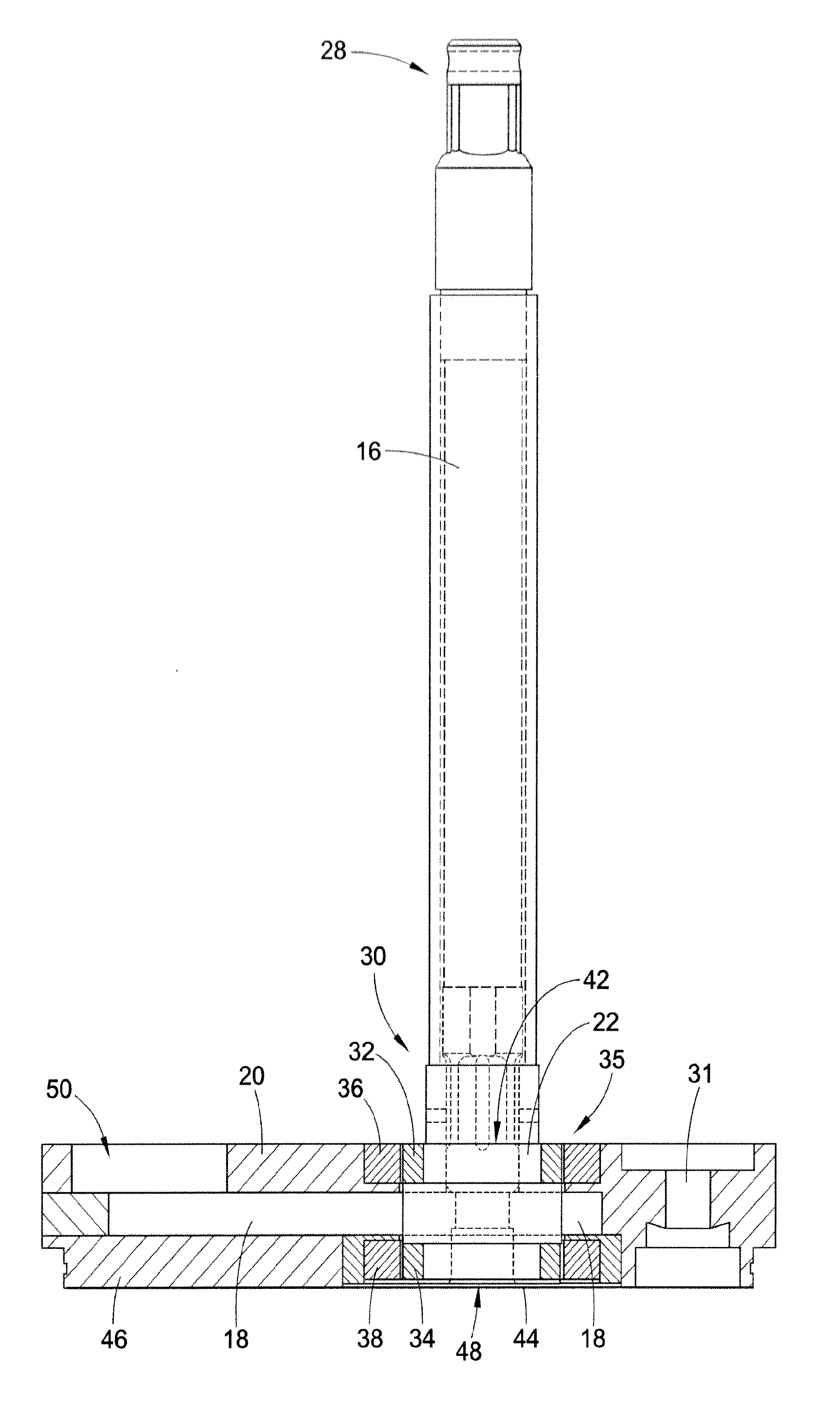
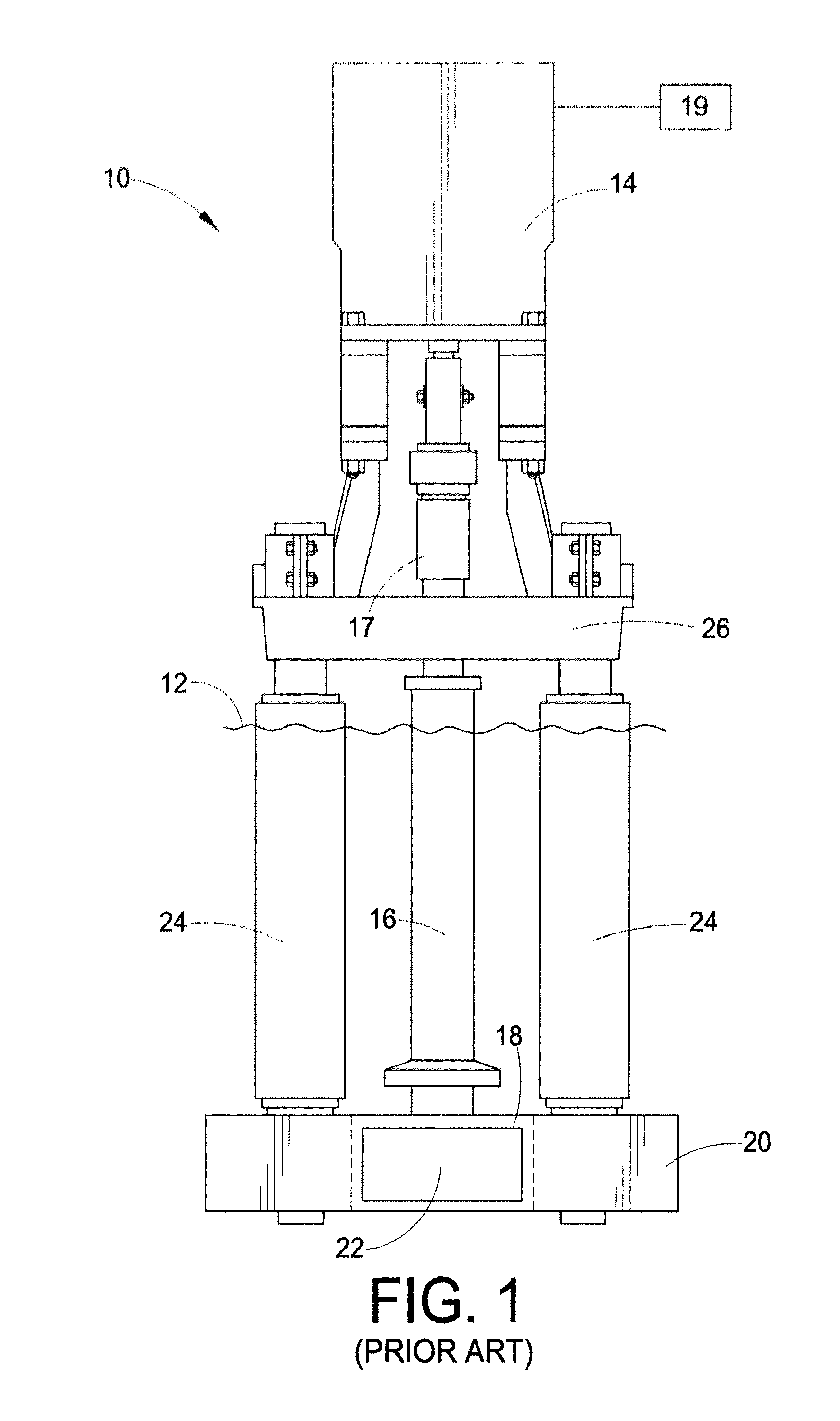
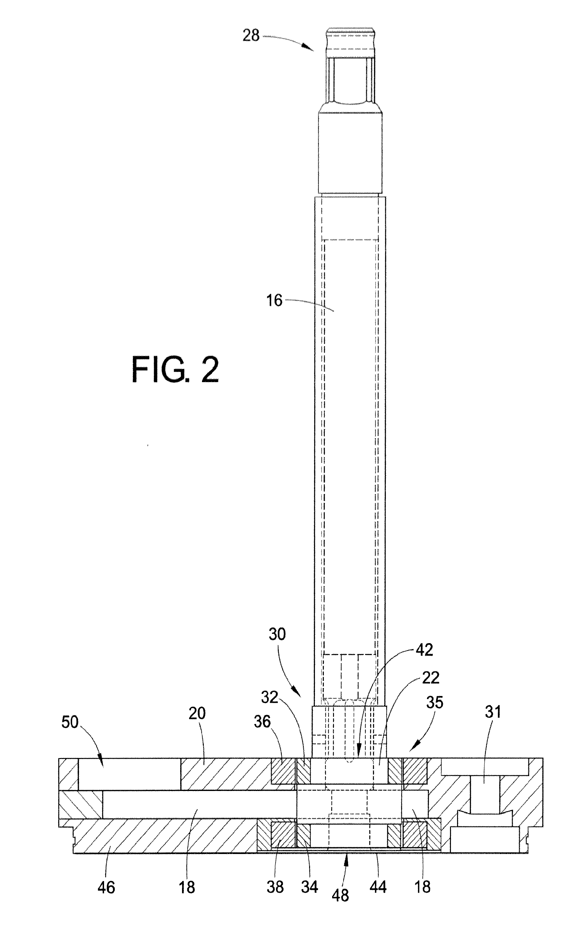
[0021]With reference to FIG. 1, an example of a molten metal pump assembly 10 submerged in a bath of molten metal 12 is displayed. The molten metal 12, such as aluminum, can be located within a furnace or tank (not shown). The molten metal pump assembly 10 includes a motor 14 connected to an elongated shaft 16 via coupling 17. The motor is adapted to be run at variable speed by a programmable controller 19, such as a computer or other processor. The elongated shaft 16 is connected to an impeller 22 located in the chamber 18 of a base member 20. The base member 20 is suspended by a plurality of refractory posts 24 attached to a motor mount 26. An altern...


PUM

PropertyMeasurementUnit
flow rateaaaaaaaaaa
pressureaaaaaaaaaa
circumferenceaaaaaaaaaa

Abstract

A molten metal pump assembly (10) and method to fill complex molds with molten metal, such as aluminum. The pump assembly includes an elongated shaft (16) connecting a motor (14) to an impeller (22). The impeller is housed within a chamber (18) of a base member such that rotation of the impeller draws molten metal into the chamber at an inlet (48) and forces molten aluminum through an outlet (50). A first bearing (36) is adapted to support the rotation of the impeller at a first radial edge (32) and a second bearing (38) is adapted to support the rotation of the impeller at a second radial edge. A bypass gap (60) is interposed between the second bearing and the second radial edge. Molten metal leaks through the bypass gap at a predetermined rate to manipulate a flow rate and a head pressure of the molten metal such that precise control of the flow rate is achieved.

Description

BACKGROUND[0001]The present exemplary embodiment relates to a pump assembly to pump molten metal. It finds particular application in conjunction with a shaft and impeller assembly for variable pressure pumps for filling molds with molten metal, and will be described with particular reference thereto. However, it is to be appreciated that the present exemplary embodiment is also amenable to other like applications.[0002]At times it is necessary to move metals in their liquid or molten form. Molten metal pumps are utilized to transfer or recirculate molten metal through a system of pipes or within a storage vessel. These pumps generally include a motor supported by a base member having a rotatable elongated shaft extending into a body of molten metal to rotate an impeller. The base member is submerged in the molten metal and includes a housing or pump chamber having the impeller located therein. The motor is supported by a platform that is rigidly attached to a plurality of structural...

Claims


Application Information

Patent Timeline
Patent Type & Authority Applications(United States)
IPC IPC(8): F04D7/00
CPCF04D7/00B22D17/02F04D7/065F04D29/0473B22D23/00B22D39/02F04D7/04F04D7/06F04D29/047F04D3/005
Inventor TIPTON, JON
Owner PYROTECK INC
Why Eureka
Try Eureka