catheter

Active Publication Date: 2014-02-13
ASAHI INTECC CO LTD
View PDF8 Cites 1 Cited by
  • Summary
  • Abstract
  • Description
  • Claims
  • Application Information

AI Technical Summary

Benefits of technology

[0009]Accordingly, the present invention has been developed in view of the above circumstances and provides a catheter

Problems solved by technology

However, with the above described method of joining the first wires and the second wires together at the intersection points, it is difficult to join the first wires and the second wires together with high joint strength.
If, however, the thicknesses of first wires and second wires of the braid are reduced for this purpose, a necessary joint strength between the first wires and the second wires is not sufficiently secured by only joining the first wires and the second wires together at the intersection points.
If, for securing a necessary joint strength, the first wires and t

Method used


Image

  • catheter
  • catheter
  • catheter

Examples


Example

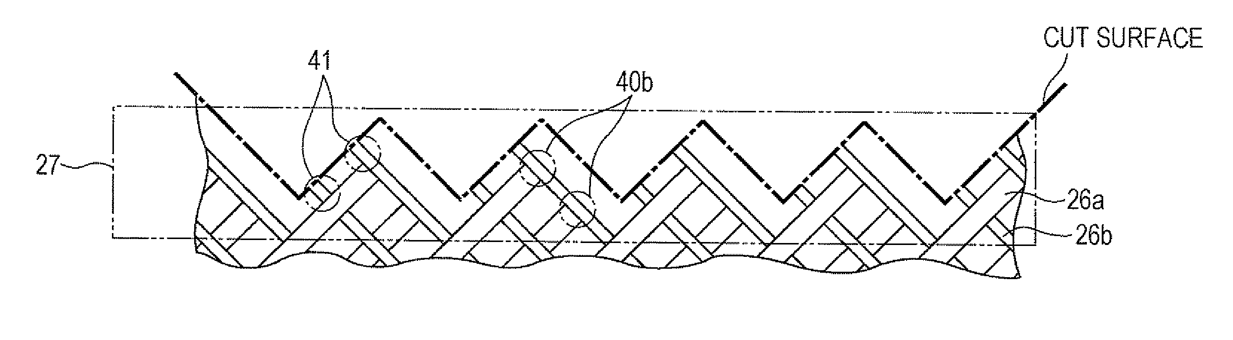
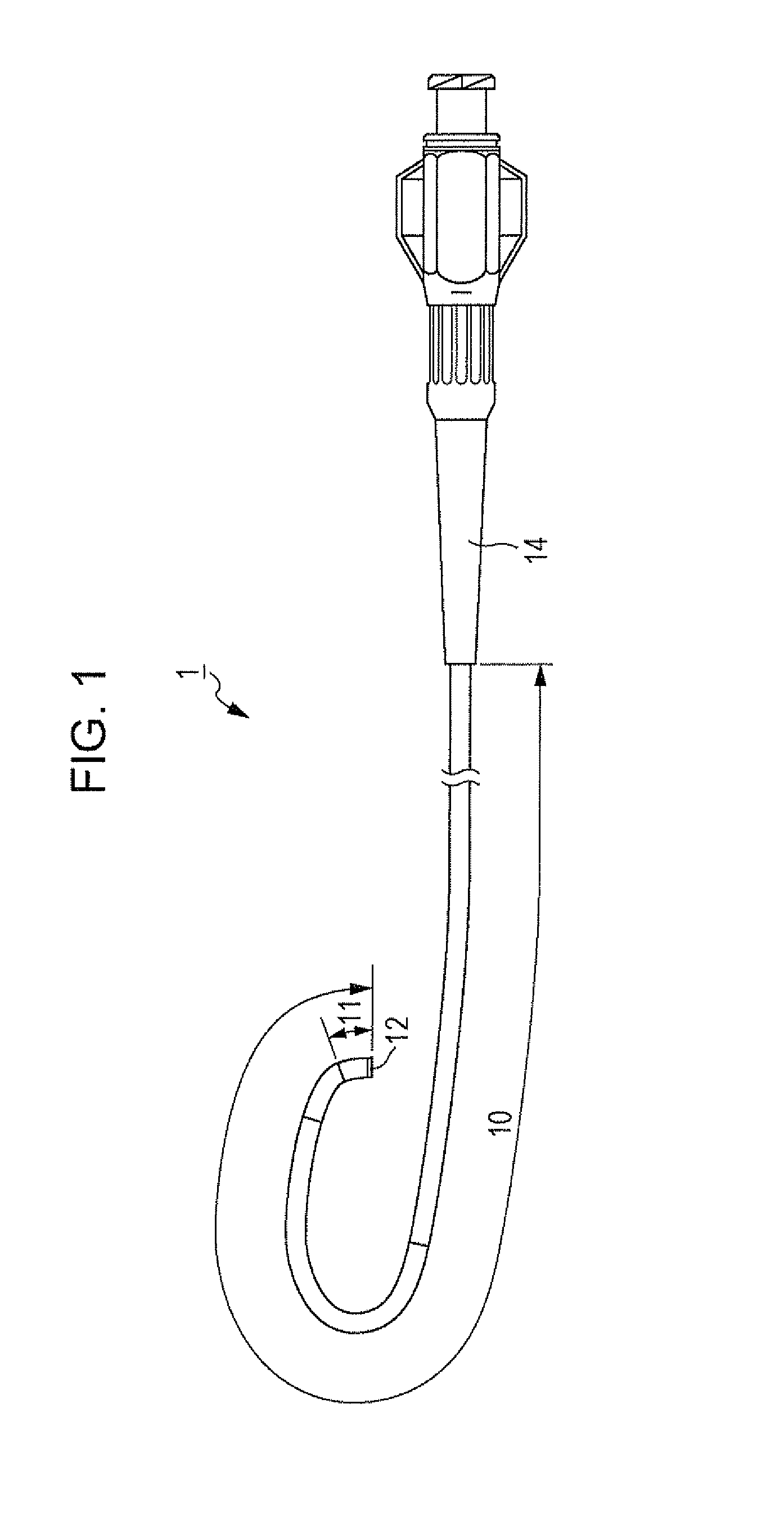
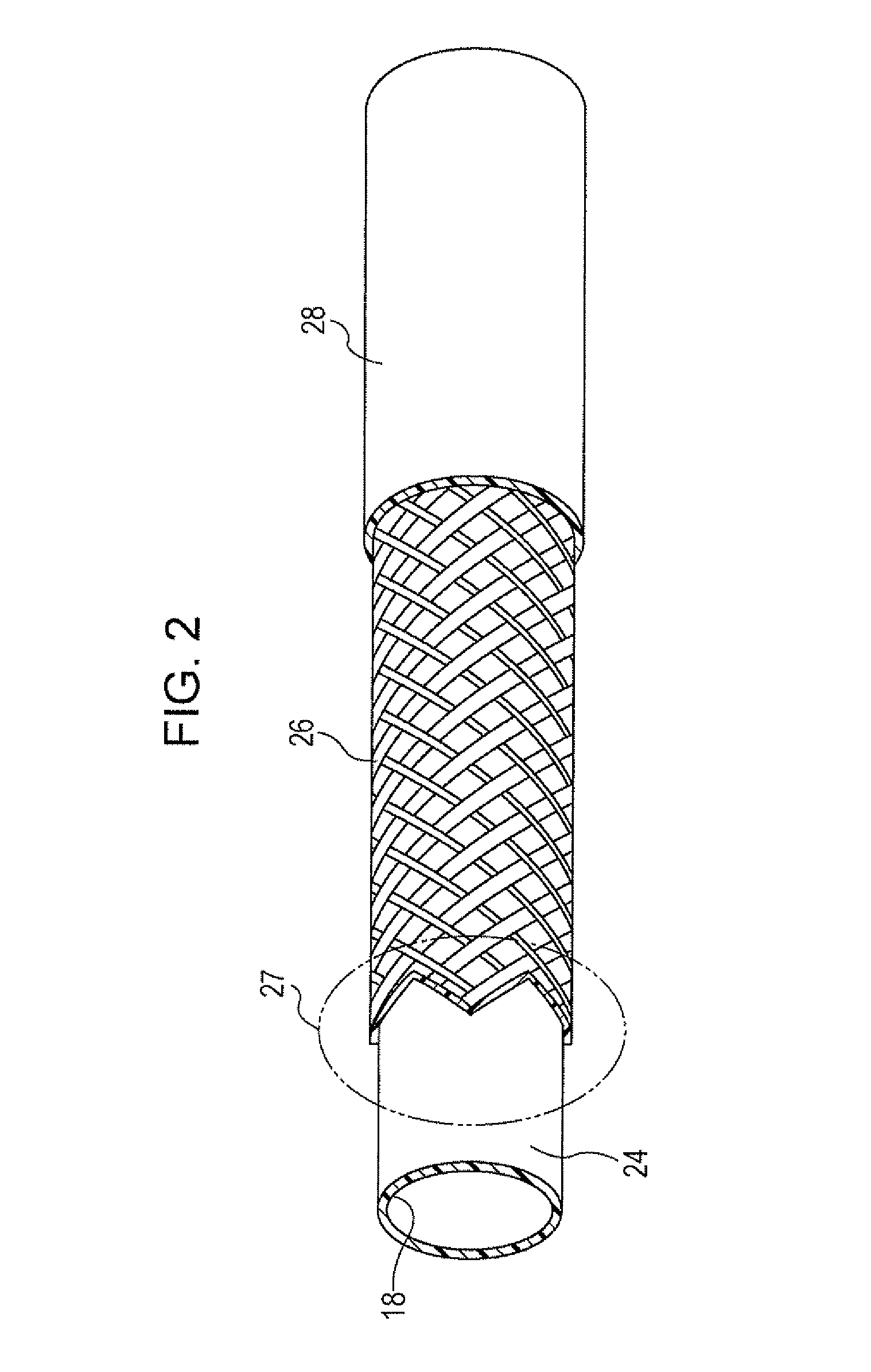
[0022]Referring to FIGS. 1 to 9B, a catheter 1 according to an embodiment will be described as an example. In FIGS. 1, 2, and 3, the left side is a distal side (far side) that is inserted into a body while the right side is a proximal side (a near side or a base side) that is manipulated by a technician such as a doctor. For ease of understanding, small components such as first wires 26a and second wires 26b of a braid 26, which are described below, are slightly exaggerated throughout the drawings relative to the dimensions of other components.

[0023]The catheter 1 illustrated in FIG. 1 is a tubular medical device having a full length of approximately 1200 mm. The catheter I mainly includes a catheter body 10 having flexibility, a distal tip 12 bonded to a distal end portion 11 of the catheter body 10, and a connector 14 fixed to a proximal portion of the catheter body 10.

[0024]As illustrated in FIGS. 2 and 3, the catheter body 10 includes an inner layer 24, a braid 26 serving as a r...


PUM

PropertyMeasurementUnit
Thicknessaaaaaaaaaa
Angleaaaaaaaaaa
Widthaaaaaaaaaa

Abstract

A body of a catheter includes an inner layer, a braid, and an outer layer. The braid includes first and second wires. The first and second wires can be joined together such that the distal end portion of the first wire winds itself around a side surface of the second wire. A joint includes a first joint portion positioned at the intersection point, a second joint portion positioned beyond the first wire in a width direction of the first wire, and a third joint portion positioned beyond the second wire in a width direction of the second wire. Thus, even when the first and second wires have small thicknesses for size reduction of the braid, the first and second wires can be joined together with high joint strength by increasing the area of the second joint portion or the thickness of the third joint portion.

Description

CROSS-REFERENCE TO RELATED APPLICATION[0001]This application claims priority to Japanese Patent Application No. 2012-174528 filed in the Japan Patent Office on Aug. 7, 2012, the entirety of which is hereby incorporated by reference.BACKGROUND OF THE INVENTION[0002]1. Field of the Invention[0003]The disclosed embodiments relate to medical devices. More specifically, the disclosed embodiments relate to catheters that are inserted into blood vessels or the like.[0004]2. Description of Related Art[0005]A catheter that is inserted into a tubular organ, such as a blood vessel, an alimentary canal, or a ureter, or an internal bodily tissue, structurally includes an inner layer (base tube) made of a resin, an outer layer surrounding the outer periphery of the inner layer and made of a resin, and a braid (reinforcement layer) interposed between the inner layer and the outer layer. This braid is formed by weaving wires made of a metal such as copper or stainless steel together in consideratio...

Claims


Application Information

Patent Timeline
IPC IPC(8): A61M25/00
CPCA61M25/0012B29C70/22A61M25/001B29C70/54A61M25/005B29L2031/7542A61M25/0108A61M25/0054A61M25/0045A61M25/0041
Inventor KUWADA, SHUICHIOSHIMA, FUMIYOSHIYAMADA, KAZUTAKA
Owner ASAHI INTECC CO LTD
Why Eureka
Try Eureka