Method for improving strength of steel-niobium laser welding joint

A joint strength, laser welding technology, applied in laser welding equipment, welding/welding/cutting items, welding equipment, etc., can solve the problem of low joint strength, improve joint strength, inhibit the formation of intermetallic compounds, and improve tensile strength the effect of strength

Inactive Publication Date: 2017-07-18
JIANGSU UNIV OF SCI & TECH
View PDF7 Cites 3 Cited by
  • Summary
  • Abstract
  • Description
  • Claims
  • Application Information

AI Technical Summary

Problems solved by technology

[0005] The purpose of the present invention is to provide a method for improving the joint strength of steel niobium

Method used


Image

  • Method for improving strength of steel-niobium laser welding joint
  • Method for improving strength of steel-niobium laser welding joint
  • Method for improving strength of steel-niobium laser welding joint

Examples


Embodiment 1

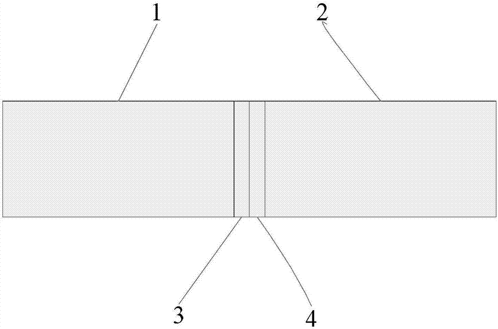
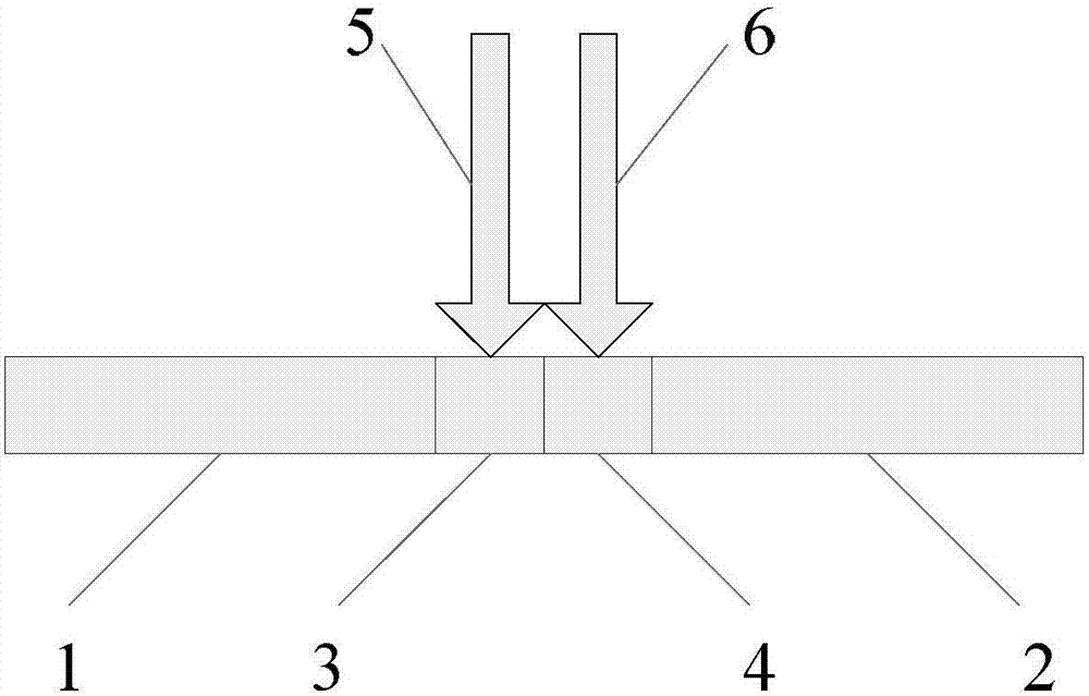
[0026] Embodiment 1: the welding method of this embodiment is realized according to the following steps (see figure 1 , figure 2 ):

[0027] (1) The base metal is Nb521 alloy and 304 stainless steel, and the size is 50mm×25mm×2mm. The middle layer is pure copper plate and pure tantalum plate, the size is 50mm×2mm×1mm;

[0028] (2) Polish the surface of the stainless steel plate, niobium plate, copper sheet and tantalum sheet with 80# water-resistant sandpaper to remove the surface oxide film and oil stains, and then use absorbent cotton to clean the surface of the test piece with acetone and alcohol respectively to ensure that the surface of the material is clean. pollute;

[0029] (3) The copper sheet and the tantalum sheet are pre-placed between the steel plate and the niobium sheet as a composite intermediate layer, the copper sheet is located on the side of the steel base material, and the tantalum sheet is located on the side of the niobium base material, that is, the...

Embodiment 2

[0032] Embodiment 2: The difference between this embodiment and Embodiment 1 is that the thickness of the copper sheet and the tantalum sheet in the intermediate layer is 0.8 mm. Others are the same as in Example 1.

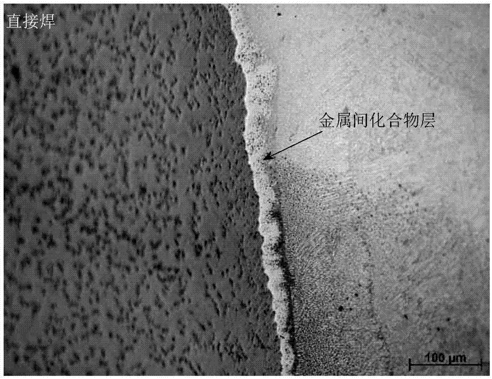
[0033] No intermetallic compound is formed in the welded joint of this embodiment. The tensile strength of the joint is 136MPa.

Embodiment 3

[0034] Embodiment 3: The difference between this embodiment and Embodiment 1 is that the thickness of the copper sheet and the tantalum sheet in the intermediate layer is 0.6 mm. Others are the same as in Example 1.

[0035] No intermetallic compound is formed in the welded joint of this embodiment. The tensile strength of the joint is 121MPa.


PUM

PropertyMeasurementUnit
Thicknessaaaaaaaaaa
Thicknessaaaaaaaaaa
Tensile strengthaaaaaaaaaa

Abstract

The invention provides a method for improving strength of a steel-niobium laser welding joint, and relates to a steel-niobium laser welding process. The method is used for solving the problem that an existing steel-niobium welding method is low in joint strength. Firstly, a metal transition layer is arranged between a steel plate and a niobium plate in advance to form a to-be-welded piece; then, welding is conducted, and the metal transition layer is any one of a composite layer composed of a copper sheet and a tantalum sheet, a copper sheet layer or a silver sheet layer; when the composite layer composed of the copper sheet and the tantalum sheet is used as transition metal, welding is conducted through a two-pass welding process, a first-pass laser beam acts on the center of the copper layer, and a second-pass laser beam acts on the center of the tantalum layer; and when the copper sheet layer or the silver sheet layer is used as the metal transition layer, welding is conducted through a single-pass welding process, and a laser beam acts on the center of the copper layer. By means of the method, generation of intermetallic compounds in the steel-niobium welding joint can be restrained, and the joint strength can be remarkably improved. The method is suitable for manufacturing steel-niobium composite components.

Description

technical field [0001] The invention belongs to the field of dissimilar metal welding, and in particular relates to a method for improving the strength of steel niobium laser welding joints. Background technique [0002] The steel-niobium composite welded structure can increase the working temperature of the aeroengine, reduce its weight, and make the aeroengine have a higher thrust-to-weight ratio, which has broad application prospects in the aerospace field. However, a large number of continuously distributed brittle intermetallic compounds are easily formed in steel niobium welded joints, which significantly reduces the joint strength and even produces cracks after welding. Therefore, controlling the intermetallic compounds in welded joints is a key issue in realizing reliable welding of niobium steel. [0003] Previously, our research group used a tungsten / copper composite intermediate layer to be pre-placed between the steel plate and the niobium plate to form the weld...

Claims


Application Information

Patent Timeline
IPC IPC(8): B23K26/24B23K26/14B23K26/211B23K26/323
CPCB23K26/24B23K26/14B23K26/211B23K26/323B23K2103/18
Inventor 石铭霄陈书锦刘大双李瑞峰胡庆贤赵健王威林
Owner JIANGSU UNIV OF SCI & TECH
Why Eureka
Try Eureka