Solar energy systems using external reflectors
a solar energy system and reflector technology, applied in the field of solar energy technology, can solve the problems of ignoring the utilization of light by traditional fresco lenses, affecting so as to improve the utilization rate of light, and improve the effect of light transmission
- Summary
- Abstract
- Description
- Claims
- Application Information
AI Technical Summary
Benefits of technology
Problems solved by technology
Method used
Image

Examples
first embodiment
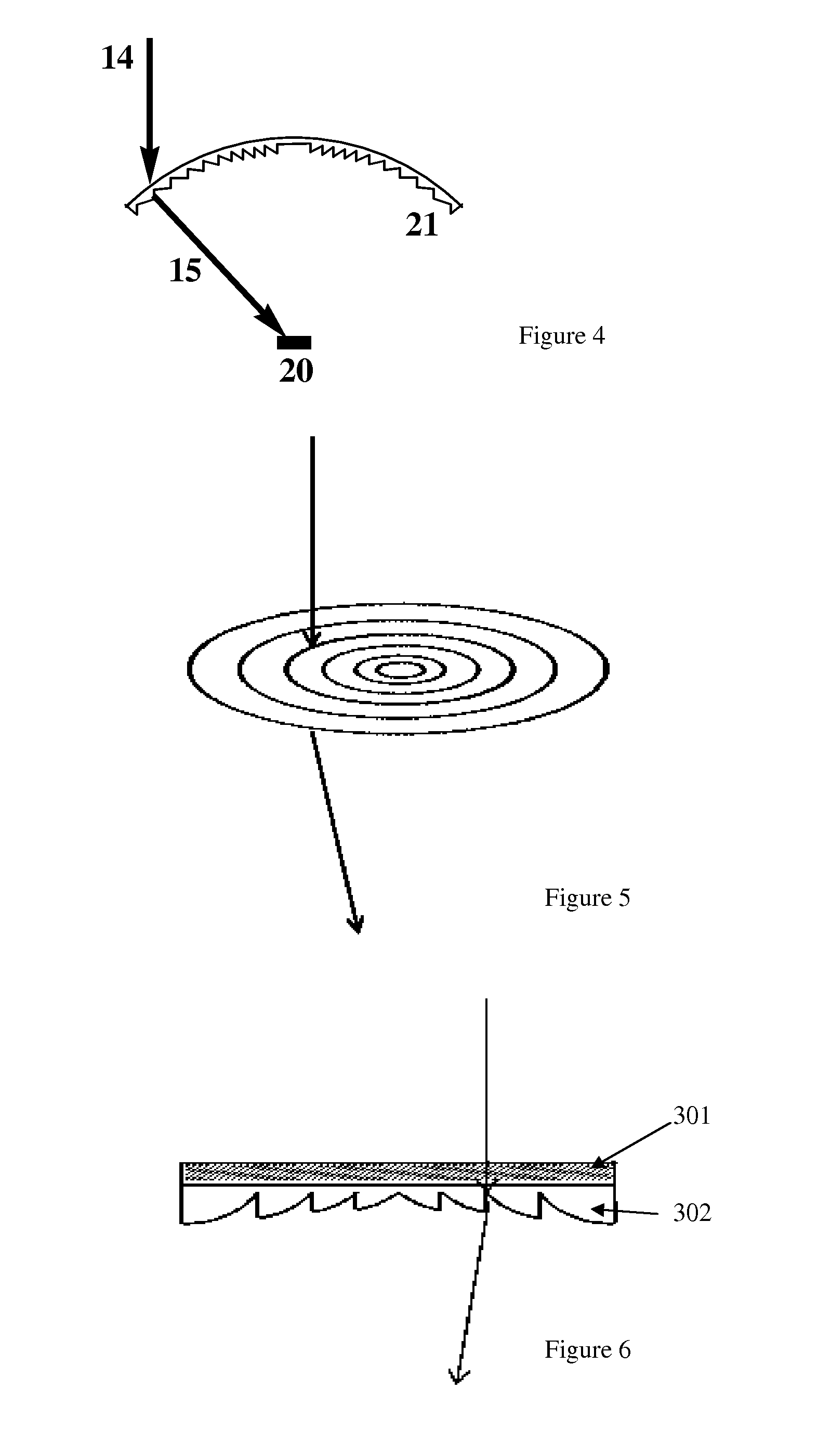
[0035]The concentrating photovoltaic systems shown in FIGS. 7-8 includes anti-reflection film 301, quasi-Fresnel concave lens 302, reflector 303, filling material 304 and PV modules 305. The lens has a substantially planar shape. The film 301 is located above the lens 302 and may be coated on the upper flat surface of the lens. The reflector 303 is disposed below the lens 302, and the PV modules 305 are disposed below the reflector. The material of the anti-reflection film 301 may be porous SiO2 or MgF2, and the material of the quasi-Fresnel lens 302 may be glass. The interface between the antireflection film 301 and the quasi-Fresnel concave lens 302 can increase the transmittance of the incident light through the quasi-Fresnel concave lens 302, and can also help create secondary or multiple reflections to reflect light back to the PV modules. The inner surface of the reflector 303 may be coated with a reflective film, which may be Al, Ag, or other metal-dielectric film. The reflec...
second embodiment
[0039]A concentrator photovoltaic system shown in FIG. 9 includes a condenser system and photovoltaic modules. This system is similar to the one shown in FIGS. 7-8 in that it includes anti-reflection film 301, quasi-Fresnel concave lens 302, reflector 303′, filling material 304 and PV modules 305, the difference being the anti-reflection film 301 and quasi-Fresnel concave lens 302 are located mid-way inside the truncated-cone shaped reflector 303′. If the distance from the top of the reflector 303′ to the quasi-Fresnel concave lens 302 is L1, the distance from the quasi-Fresnel concave lens to the photovoltaic module 305 is L2, and the angle between the sidewall of the reflector 303′ and the photovoltaic modules is Φ, the concentration ratio of the entire condenser system can be adjusted by adjusting the size of the L1 / L2 ratio and the angle Φ. The adjustment range of the angle Φ is about 120°-150°.
[0040]The above system can effectively improve the incident flux density and reduce t...
third embodiment
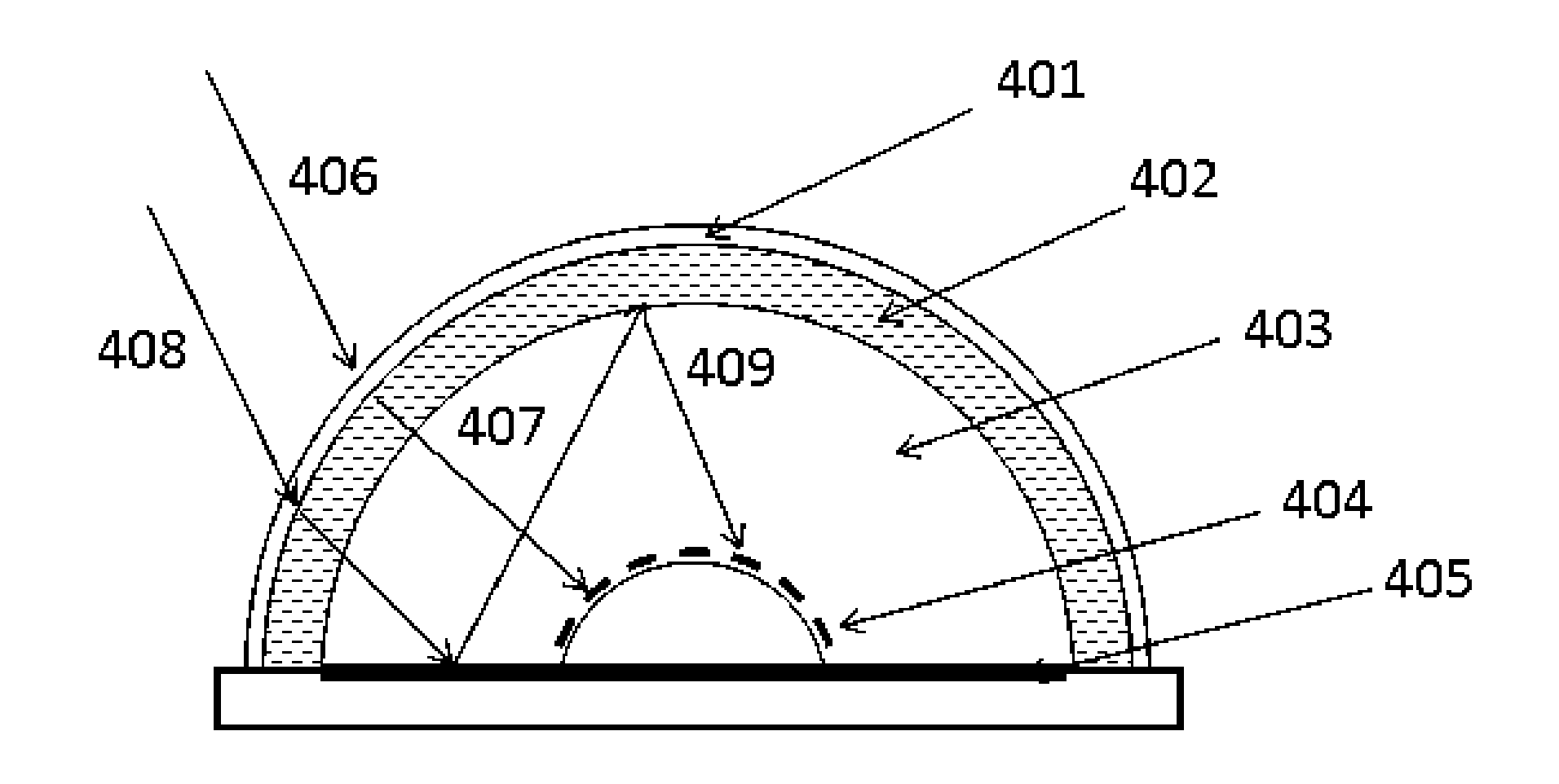
[0042]A concentrator photovoltaic system shown in FIG. 10 includes a condenser system and photovoltaic modules. The condenser system includes a hemispherical quasi-Fresnel lens 402 coated with anti-reflection film 401 and a planar reflector 405. The PV module 404 is located in the focal sphere of the hemispherical Fresnel lens 402, and a high refractive index optical resin 403 is filled between the quasi-Fresnel lens and the PV module. The PV modules 404 can be composed of one flexible cell or many flat cells. The reflector 405 is disposed in a plane at the base of the hemispherical quasi-Fresnel lens 402 and covers substantially the entire areas between the PV module and the circular base of the quasi-Fresnel lens. In the illustrated example, the incident light 406 passes through the condenser components (anti-reflection film 401 and lens 402) to form a beam 407 illuminating on the cell (PV module) 404. The incident light 408 is refracted to the reflector 405 by the condenser compo...
PUM
 Abstract
Description
Claims
Application Information
 - R&D
- Intellectual Property
- Life Sciences
- Materials
- Tech Scout
- Unparalleled Data Quality
- Higher Quality Content
- 60% Fewer Hallucinations
Browse by: Latest US Patents, China's latest patents, Technical Efficacy Thesaurus, Application Domain, Technology Topic, Popular Technical Reports.
© 2025 PatSnap. All rights reserved.Legal|Privacy policy|Modern Slavery Act Transparency Statement|Sitemap|About US| Contact US: help@patsnap.com