Piston valve of shock absorber

a technology of shock absorber and piston valve, which is applied in the direction of shock absorber, vibration damper, spring/damper, etc., can solve the problems of insufficient relief of momentary low frequency and high amplitude shock, limited degree of design freedom of shock absorber, etc., and achieves the effect of improving the emotional quality

Active Publication Date: 2014-02-20
HL MANDO CORP
View PDF12 Cites 21 Cited by
  • Summary
  • Abstract
  • Description
  • Claims
  • Application Information

AI Technical Summary

Benefits of technology

[0030]Since the piston valve of the shock absorber according to the exemplary embodiment of the present invention includes a pressure sensitive main valve unit, a sub-valve unit, and a frequency sensitive valve unit, the piston valve can achieve both an effect of varying an attenuation force according to a pressure and an effect of an attenuation force according to a frequency region.
[0031]In addition, since the main valve unit is coupled to the outer circumferential surface of the valve housing, and the frequency sensitive valve unit and the sub-valve unit are installed together within the valve housing, it is possible to solve the problem of increase of the entire length in the conventional shock absorber due to the serial installation of the pressure sensitive valve and the frequency sensitive valve.
[0032]Further, since a momentary low frequency and high amplitude shock may be sufficiently adsorbed and relieved and occurrence of spring friction sounds in the frequency sensitive valve may be prevented, an emotional quality improving effect may be obtained.

Problems solved by technology

However, when the moving stroke of the piston rod 3 is small or at a high frequency shock region, a proper attenuation force may not be obtained.
In addition, the degree of design freedom of the shock absorber 20 may be limited due to the increase of manufacturing time and costs and the problem of installation space.
However, since the shock absorber 20 illustrated in FIG. 2 relies only on the operation of the conventional piston valve 25, such a momentary low frequency and high amplitude shock cannot be sufficiently relieved.
Furthermore, there is a problem in that, when the balancing weight 36 is moved up and down due to a high frequency vibration, friction sounds may be generated due to the contact between the windings of the springs 37 and 38.

Method used


Image

  • Piston valve of shock absorber
  • Piston valve of shock absorber
  • Piston valve of shock absorber

Examples


embodiments

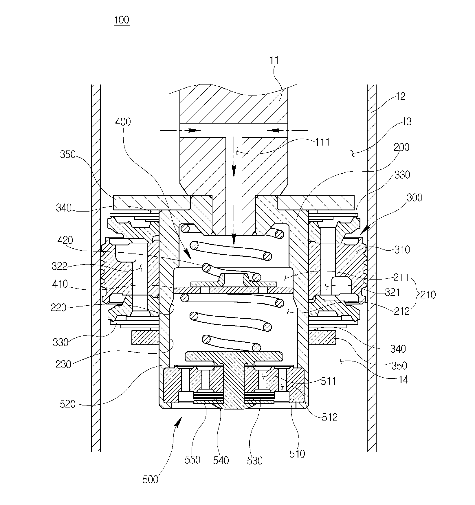
[0041]FIG. 3 is a cross-sectional view illustrating the operating state of a piston valve of a shock absorber according to an exemplary embodiment of the present invention when a high frequency shock is input, and FIG. 4 is a cross-sectional view illustrating the operating state of the piston valve of the shock absorber according to the exemplary embodiment when a low frequency shock is input.

[0042]As illustrated in FIGS. 3 and 4, a piston valve 100 of a shock absorber according to an exemplary embodiment of the present invention is coupled to the lower end of a piston rod 11 in a state in which a frequency sensitive valve unit 400 is installed inside of a main valve unit 300.

[0043]More specifically, the piston valve 100 of the shock absorber according to the exemplary embodiment of the present invention includes a valve housing 200 coupled to the lower end of the piston rod 11, a frequency sensitive valve unit 400 installed in a space 210 within the valve housing 200, and a main va...


PUM


Abstract

Provided is a piston valve of a shock absorber which can achieve both an effect of varying an attenuation force according to a pressure and an effect of varying an attenuation force according to a frequency region. The piston valve includes: a main valve unit coupled to a lower end of a piston rod formed with an orifice hole, to divide an inside of a cylinder into an extension chamber and a compression chamber, the main valve unit generating an attenuation force according to a difference of pressure between the extension chamber and the compression chamber; and a frequency sensitive valve unit installed at one side of the main valve unit and configured to generate an attenuation force according to a frequency of hydraulic fluid delivered through the orifice hole of the piston rod, wherein the frequency sensitive valve unit is installed within the main valve unit.

Description

BACKGROUND OF THE INVENTION[0001]1. Field of the Invention[0002]The present invention relates to a piston valve, and more particularly, to a piston valve of a shock absorber in which a frequency sensitive valve unit is installed inside of a pressure sensitive main valve unit to reduce the entire length of the piston valve.[0003]2. Description of the Prior Art[0004]In general, a vehicle continuously receives vibration or a shock from a road surface through the wheels during driving. Thus, a shock absorbing device is provided between the vehicle body and the vehicle axle so as to prevent the shock or vibration from being directly transferred to the vehicle body, thereby improving ride comfort. In addition, the shock absorbing device suppresses the irregular vibration of the vehicle body, so as to enhance the driving stability.[0005]A suspension system, which is a general name of a connection device between a vehicle axle and a vehicle body including the shock absorbing device as descr...

Claims


Application Information

Patent Timeline
Patent Type & Authority Applications(United States)
IPC IPC(8): F16F9/34
CPCF16F9/34F16F9/5126F16F9/32F16F9/50
Inventor LEE, JIN KEEYOON, KYONG HAG
Owner HL MANDO CORP
Why Eureka
Try Eureka