Graphene nanoribbon composites and methods of making the same

Inactive Publication Date: 2014-02-20
RICE UNIV
View PDF10 Cites 5 Cited by
  • Summary
  • Abstract
  • Description
  • Claims
  • Application Information

AI Technical Summary

Benefits of technology

[0006]In some embodiments, the polymer matrix of the composite includes at least one of polyurethanes, epoxy resins, polyimides, nylons, polyesters, acrylic resins, polycyanoacrylates, polystyrenes, polybutadienes, synthetic rubbers, natural rubbers, and combinations thereof. In more specific embodiments, the

Problems solved by technology

Present day adhesives have numerous limitations.
Such limitations include poor co

Method used


Image

  • Graphene nanoribbon composites and methods of making the same
  • Graphene nanoribbon composites and methods of making the same
  • Graphene nanoribbon composites and methods of making the same

Examples


Example

EXAMPLE 1

Synthesis of Functionalized Graphene Nanoribbons

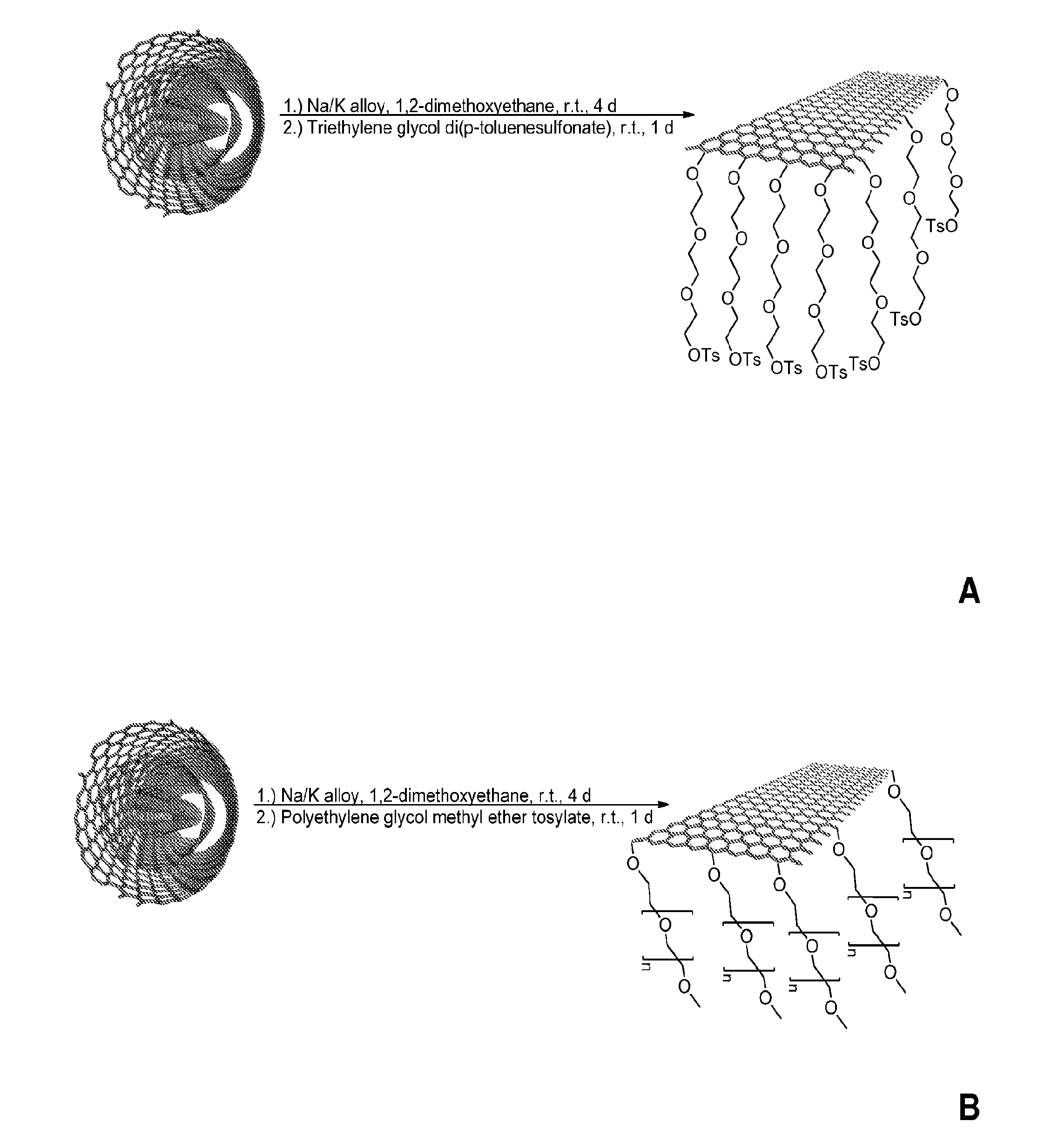
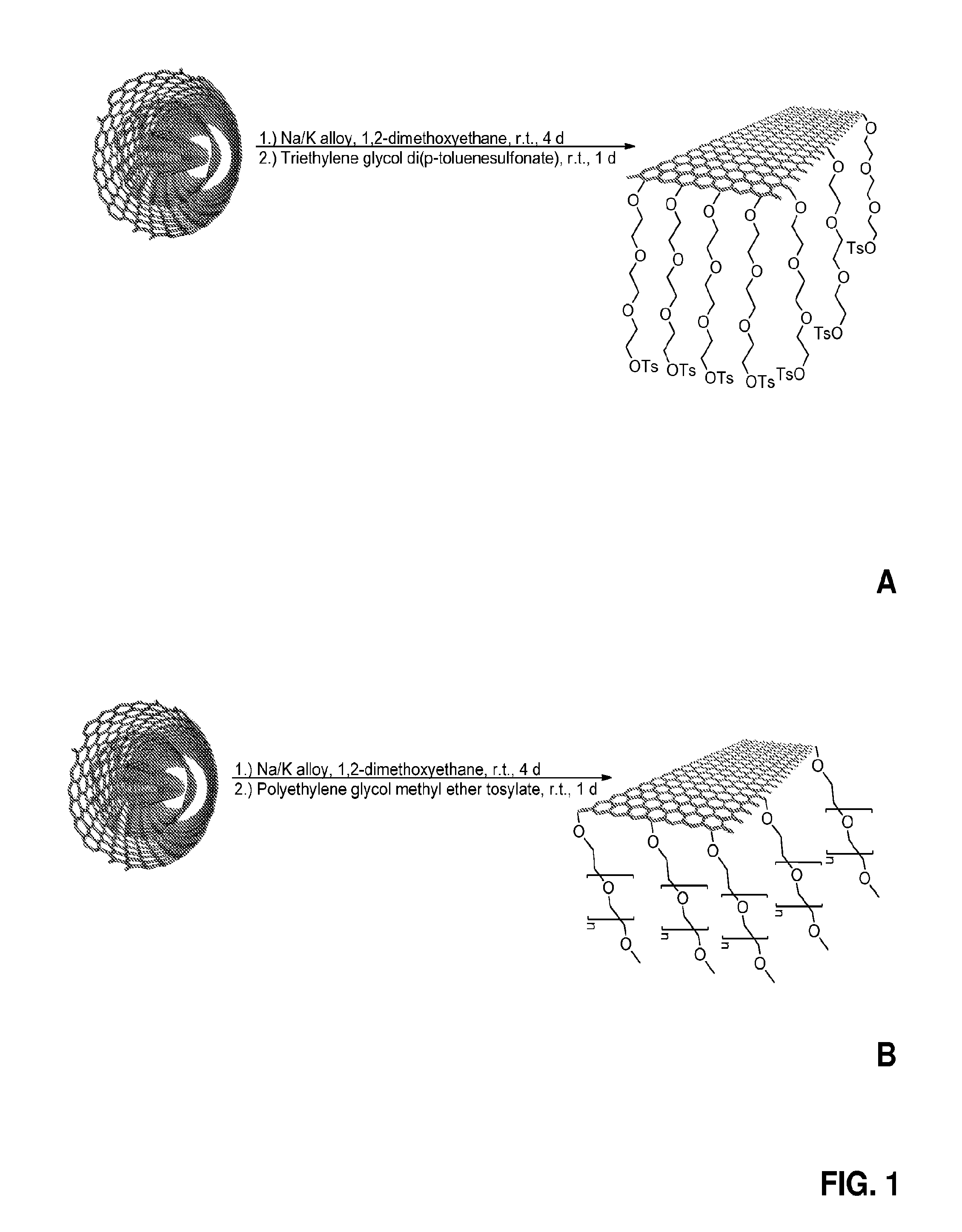
[0072]The graphene nanoribbons were synthesized by chemical splitting of multi-walled nanotubes with NaK vapor. See, e.g., ACS Nano 5, 968-74 (2011). In a typical synthesis, 0.45 mg of NaK (1:9 by mass) was added into 100 mg multi-walled carbon nanotubes (NTL Composites) with 40 mL 1,2-dimethoxyethane (Sigma Aldrich) added as a solvent. The reaction mixture was stirred on a magnetic stirrer for at least 3 days. In order to functionalize the nanoribbons, a certain amount of electrophilic organic compounds were added and stirred for a day. The reaction mixture was washed with ethanol, H2O, ethanol, THF, and ether in that order.

[0073]The synthetic schemes for the functionalized graphene nanoribbons are shown in FIG. 1. In this Example, two graphene nanoribbons were used. GNR1 (FIG. 1A) was functionalized with triethylene glycol di(p-toluenesulfonate). GNR2 (FIG. 1B) was functionalized with polyethylene glycol methyl ether tosyla...

Example

EXAMPLE 2

Processing of Nanocomposites

[0077]Nanocomposite samples were made by adding a certain weight percentage of functionalized graphene nanoribbons from Example 1 into an epoxy resin (Aeromarine #300). This was followed by mixing with a rod. The sample was then bath sonicated for 1 hour using a Cole-Parmer Ultrasonic Cleaner. Next, a hardener (Aeromarine #21) was added to the mixture. The mixture was then bath sonicated for 10 minutes. Thereafter, the nanocomposite mixture was cast into a silicone mold and cured for 3 hours at 70° C. on a hot plate. This process worked for any suitable epoxy / hardener combination. Images of the formed composites are shown in FIG. 3.

Example

EXAMPLE 3

DC Conductivity Measurements

[0078]In order to measure conductivity of the formed nanocomposites, 70 nm Pt contacts were sputtered on the top and bottom of the nanocomposite samples in order to reduce contact resistance during measurements. Next, a CEN-TECH Digital Multimeter with a two point probe was used to measure the resistance across the sample.

[0079]Conductivity was determined from two-probe resistance measurements after taking account of the shape and size of the composite. The conductivity of the nanocomposite containing GNR 1 was 0.5 S / m (resistivity, 211.4 Ωcm) at 1.3 wt % loading and 2.4 S / m (resistivity, 41.9 Ωcm) at 3.2 wt % loading. The conductivity of the nanocomposite containing GNR 2 was 3 S / m (resistivity, 29.7 Ωcm) at 3.2 wt % loading. Because the fillers are carbon materials, the conductivity would not be adversely affected over time under room conditions.

[0080]Discussion

[0081]The results achieved herein make it promising to achieve electronic circuit bo...


PUM

PropertyMeasurementUnit
Temperatureaaaaaaaaaa
Electrical conductivityaaaaaaaaaa

Abstract

In some embodiments, the present invention provides graphene nanoribbon composites that include a polymer matrix and graphene nanoribbons that are dispersed in the polymer matrix. In more specific embodiments, the polymer matrix of the composite is an epoxy matrix, and the graphene nanoribbons of the composite include functionalized graphene nanoribbons. In further embodiments, the composites of the present invention further comprise metals, such as tin, copper, gold, silver, aluminum and combinations thereof. Additional embodiments of the present invention pertain to methods of making the graphene nanoribbon composites of the present invention. In some embodiments, such methods include mixing graphene nanoribbons with polymer precursors to form a mixture, and then curing the mixture to form the composite.

Description

CROSS-REFERENCE TO RELATED APPLICATIONS[0001]This application claims priority to U.S. Provisional Patent Application No. 61 / 442,519, filed on Feb. 14, 2011. The entirety of the above-identified provisional application is incorporated herein by reference.STATEMENT REGARDING FEDERALLY SPONSORED RESEARCH[0002]This invention was made with government support under Grant No. N000014-09-1-066, awarded by the Department of Defense through the United States Navy Office of Naval Research; and Grant No. FA9550-09-1-0581, awarded by the Department of Defense through the United States Air Force Office of Scientific Research. The government has certain rights in the invention.BACKGROUND OF THE INVENTION[0003]Present day adhesives have numerous limitations. Such limitations include poor conductivity, limited adhesiveness, and limited resistance to hostile environments. Therefore, a need exists for the development of improved adhesives that are conductive, and useable in various environments where ...

Claims


Application Information

Patent Timeline
IPC IPC(8): C09J9/02
CPCC09J9/02C01B2204/06B82Y30/00B82Y40/00C01B32/184C08K3/042C08L63/00
Inventor TOUR, JAMES M.ZHU, YURAJI, ABDUL-RAHMAN O.
Owner RICE UNIV
Why Eureka
Try Eureka