Sensorized Sealing System

a sensorized sealing and sensor technology, applied in the field of sealing systems, can solve the problems of increasing the demands placed on peripheral equipment for receiving and processing different sensor signals, unable to replace seals before functionality is lost to an unacceptable degree, and unable to meet the requirements of adjusting the effect of the system

Active Publication Date: 2014-02-20
AB SKF
View PDF12 Cites 15 Cited by
  • Summary
  • Abstract
  • Description
  • Claims
  • Application Information

AI Technical Summary

Benefits of technology

[0005]It is an object of the present invention to define a sealing system provided with one or more sensors of the same kind, which can be readily adapted to measure or detect a variety of parameters associated with a sealed liquid.
[0026]If the casing is made of a material with a high reluctance, then the excitation and detection means can be located at the air side of the seal It is also possible to locate the excitation and detection means at the air side of the seal when the magneto-elastic resonator(s) are mounted to the elastomeric sealing lip. The elastomeric material of the lip e.g. NBR rubber, does not block the magnetic field. Arranging the excitation and detection means at the air side has the advantage that penetration of the seal (for wiring / cabling) is unnecessary.

Problems solved by technology

The detection of moisture is indicative of seal wear, meaning that the seal can be replaced before functionality is lost to an unacceptable degree.
The use of different types of sensors, however, adds to the cost and complexity of manufacturing a sensorized seal unit and increases the demands placed on peripheral equipment for receiving and processing different sensor signals.

Method used


Image

  • Sensorized Sealing System
  • Sensorized Sealing System
  • Sensorized Sealing System

Examples


Embodiment Construction

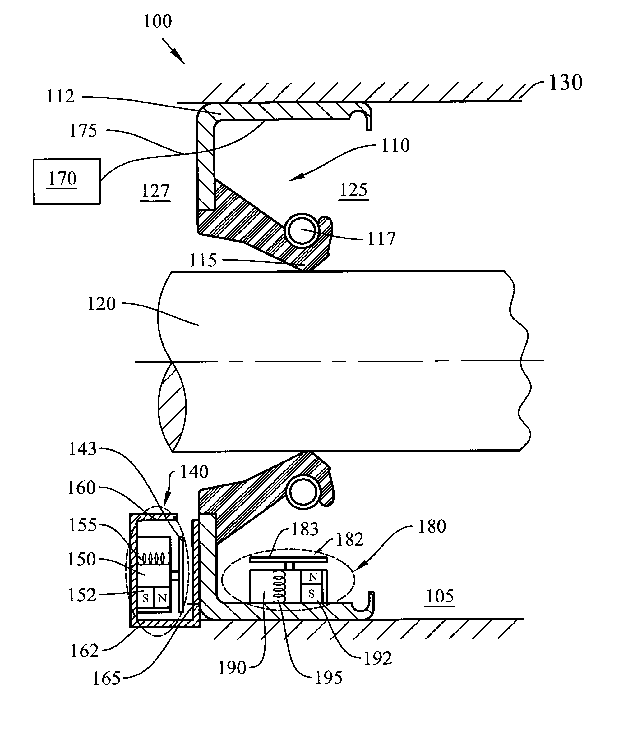
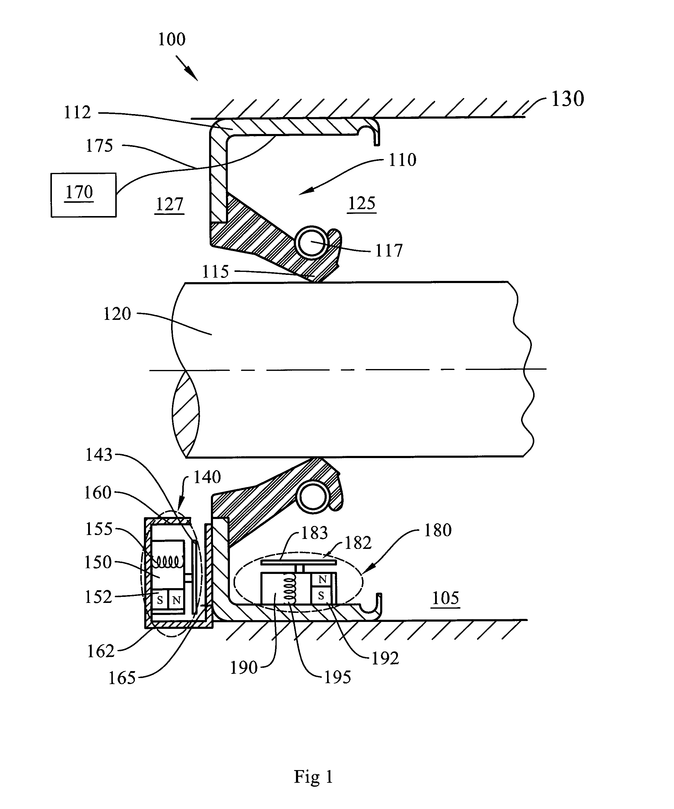
[0033]An example of a sealing system according to the invention is shown in cross- section in FIG. 1. The system 100 comprises a radial lip seal 110, which encloses an annular gap between a shaft 120 and the bore of a housing 130, and which retains an oil lubricant 105 at an axially inner side 125 of the seal. The axially inner side of the seal will be defined as an oil side 125 of the seal and an axially outer side will be defined as an air side 127 of the seal. In this example, the housing 130 is a bell housing of a gearbox in a windmill and the shaft 120 is the gearbox input shaft. Typically, the gearbox houses bearings and gears which, in use, are splash-lubricated by the oil 105.

[0034]The seal 110 comprises a metal casing 112 to which an elastomeric sealing lip 115 is bonded. Suitably, an outer circumference of the casing 112 is mounted within the housing bore, and the lip 115 bears against a counterface on the shaft 120. The seal 110 in this example further comprises a garter ...


PUM


Abstract

The present invention relates to a sealing system comprising a seal that retains a liquid in a space between two concentrically mounted and relatively rotatable components. According to the invention, the sealing system comprises at least one magneto-elastic resonance sensor for measuring at least one parameter of interest associated with the sealed liquid, based on a detected resonant frequency of the at least one sensor.

Description

FIELD OF THE INVENTION[0001]The present invention relates to a sealing system comprising a seal that retains a liquid in a space between two concentrically mounted and relatively rotatable components. More specifically, the invention relates to such a sealing system that is provided with one or more sensors for measuring a parameter or parameters of interest associated with the sealed liquid.BACKGROUND[0002]One example of a sensorized sealing device is known from US 20060006601. The device disclosed herein comprises a seal with a radial sealing lip and further comprises a measuring probe that extends into a space to be sealed. The measuring probe is exposed to a medium to be sealed, and, in one embodiment, the probe is adapted to measure the age of the sealed medium. Thus, the sealed medium—typically a lubricating oil—can be replaced before oil condition has deteriorated to an unacceptable extent.[0003]A further example of a sensorized sealing device is known from US 5648614, which ...

Claims


Application Information

Patent Timeline
Patent Type & Authority Applications(United States)
IPC IPC(8): G01M3/18G01M3/28F16J15/32
CPCG01M3/18G01M3/28F16J15/32F16J15/3296G01M3/183G01M3/2869G01M13/005
Inventor ZIEGLER, SEBASTIAN
Owner AB SKF
Why Eureka
Try Eureka