Switch-driving circuit

a technology of driving circuit and switch, applied in the direction of pulse technique, oscillation generator, power conversion system, etc., can solve the problems of increasing system cost and complexity, increasing optical fiber cost, and longer delay time, and achieve stable and reliable driving signals. fast response

Active Publication Date: 2014-02-20
DELTA ELECTRONICS INC
View PDF6 Cites 16 Cited by
  • Summary
  • Abstract
  • Description
  • Claims
  • Application Information

AI Technical Summary

Benefits of technology

[0015]In order to solve the aforesaid problem, this disclosure provides a switch-driving circuit capable of transmitting driving signals to a full-controlled power switch combination in a magnetic isolation way, so as to provide fast-response, stable and reliable driving signals to the full-controlled power switch combination.

Problems solved by technology

Therefore, the optical fibers become a bottleneck to elevate the reliability of the whole electronic system.
Secondly, each power switch component at the high-voltage side must be isolated from the low-voltage side and isolated from other power switch components at the high-voltage side as well.
Therefore, the transmission over optical fibers will significantly increase the costs and complexity of the system.
In addition, the signal transmission over optical fibers may lead to longer delay time, such that the synchronization between signals will be poor.
When the system requires highly synchronized signals, the signal transmission over optical fibers may cause some issues in the stability of power switch components.
Therefore, the traditional technology for transmitting the driving signal of the half-controlled power switch component can not be applied on the full-controlled power switch component.

Method used


Image

  • Switch-driving circuit
  • Switch-driving circuit
  • Switch-driving circuit

Examples


Embodiment Construction

[0030]In the following description, several specific details are presented to provide a thorough understanding of the embodiments of the present invention. One skilled in the relevant art will recognize, however, that the present invention can be practiced without one or more of the specific details, or in combination with other components, etc. In other instances, well-known implementations or operations are not shown or described in detail to avoid obscuring aspects of various embodiments of the present invention.

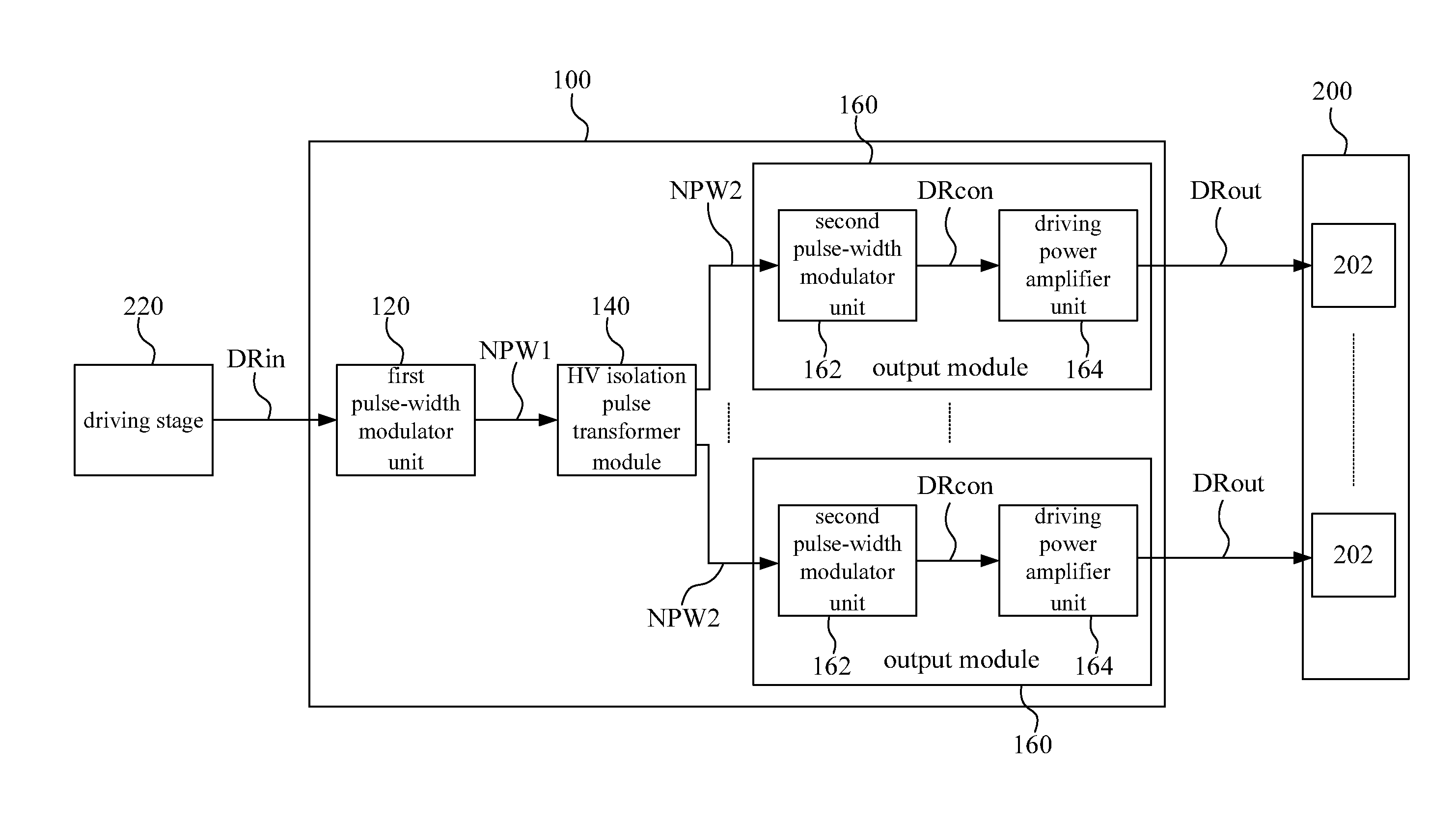
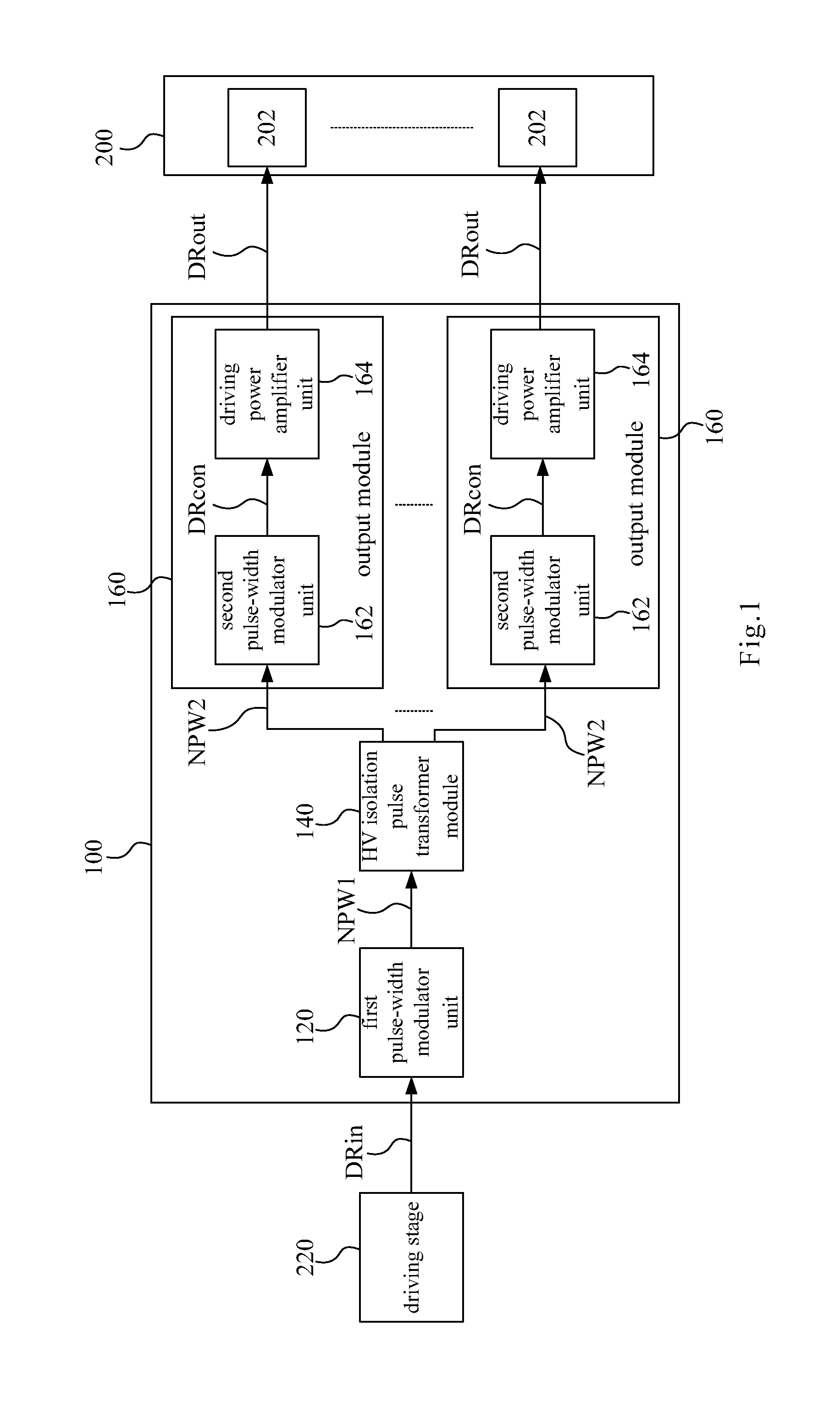
[0031]Reference is made to FIG. 1, which is a function block diagram illustrating a switch-driving circuit 100 according to an embodiment of the disclosure. As shown in FIG. 1, the switch-driving circuit 100 includes a first pulse-width modulator 120, a high-voltage isolation pulse transformer module 140 and a plurality of output modules 160. The switch-driving circuit 100 is coupled between a driving stage 220 and a full-controlled power switch combination 200, and used ...


PUM


Abstract

A switch-driving circuit suitable for driving a full-controlled power switch combination is disclosed. The switch-driving circuit includes a first pulse-width modulator, a high-voltage isolation pulse transformer module and a plurality of output modules. The high-voltage isolation pulse transformer module includes a magnetic core connected to multiple output modules in a one-to-many way, or includes multiple magnetic cores connected to multiple output modules in a one-to-one way. Each output module includes a second pulse-width modulator and a driving-power amplifier. The full-controlled power switch combination includes a plurality of full-controlled power switches. The driving-power amplifier is coupled between the second pulse-width modulator and one of the full-controlled power switches.

Description

RELATED APPLICATIONS[0001]This application claims priority to China Application Serial Number 201210297466.3, filed Aug. 20, 2012, which is herein incorporated by reference.BACKGROUND[0002]1. Technical Field[0003]The present disclosure relates to a switch-driving circuit. More particularly, the present disclosure relates to a switch-driving circuit for driving a full-controlled power switch component.[0004]2. Description of Related Art[0005]In the area of a high-power electronic device (e.g., an industrial computer, a server, an electricity equipment, etc), the reliability of the product is required seriously. The mean time between failures (MTBF) is an index used for measuring the reliability of the product. If the electronic device has a longer MTBF, it means that the electronic device is more reliable.[0006]In a traditional power supply of the electronic device, the control signals are usually transmitted via optical fibers to the high-voltage side, so as to control the power swi...

Claims


Application Information

Patent Timeline
Patent Type & Authority Applications(United States)
IPC IPC(8): H03K17/691
CPCH03K17/691H02M1/00H02M1/06H02M1/088
Inventor GAN, HONG-JIANFU, WEI-LIANGWANG, MINGYING, JIAN-PING
Owner DELTA ELECTRONICS INC
Why Eureka
Try Eureka