Touch panel and method of manufacturing same

a technology of touch panel and manufacturing method, which is applied in the field of touch panel, can solve the problems of increasing assembling time and labor cost, high assembling labor cost, and long assembling time, and achieve the effect of reducing labor and time cos

Inactive Publication Date: 2014-02-20
LIN CHIH CHUNG
View PDF4 Cites 31 Cited by
  • Summary
  • Abstract
  • Description
  • Claims
  • Application Information

AI Technical Summary

Benefits of technology

[0011]When the transparent substrate is bonded to the LCD display unit via the adhesive layer, any extra amount of the adhesive layer will flow out from between the LCD display unit and the transparent substrate to form an overflowed adhesive portion, and the overflowed adhesive portion is located in the receiving space and shielded by the raised wall portion of the backlight module. Therefore, the step of removing the overflowed adhesive portion can be saved to reduce the labor and time cost for assembling the touch panel.

Problems solved by technology

This additional procedure inevitably increases the assembling time and labor costs.
In brief, the conventional method of manufacturing the capacitive touch panel has the following disadvantages: (1) high assembling labor cost; (2) long assembling time; and (3) high bad yield.

Method used


Image

  • Touch panel and method of manufacturing same
  • Touch panel and method of manufacturing same
  • Touch panel and method of manufacturing same

Examples


Embodiment Construction

[0020]The present invention will now be described with some preferred embodiments thereof and with reference to the accompanying drawings. For the purpose of easy to understand, elements that are the same in the preferred embodiments are denoted by the same reference numerals.

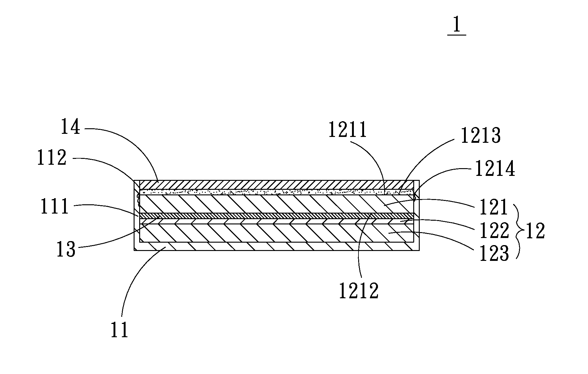
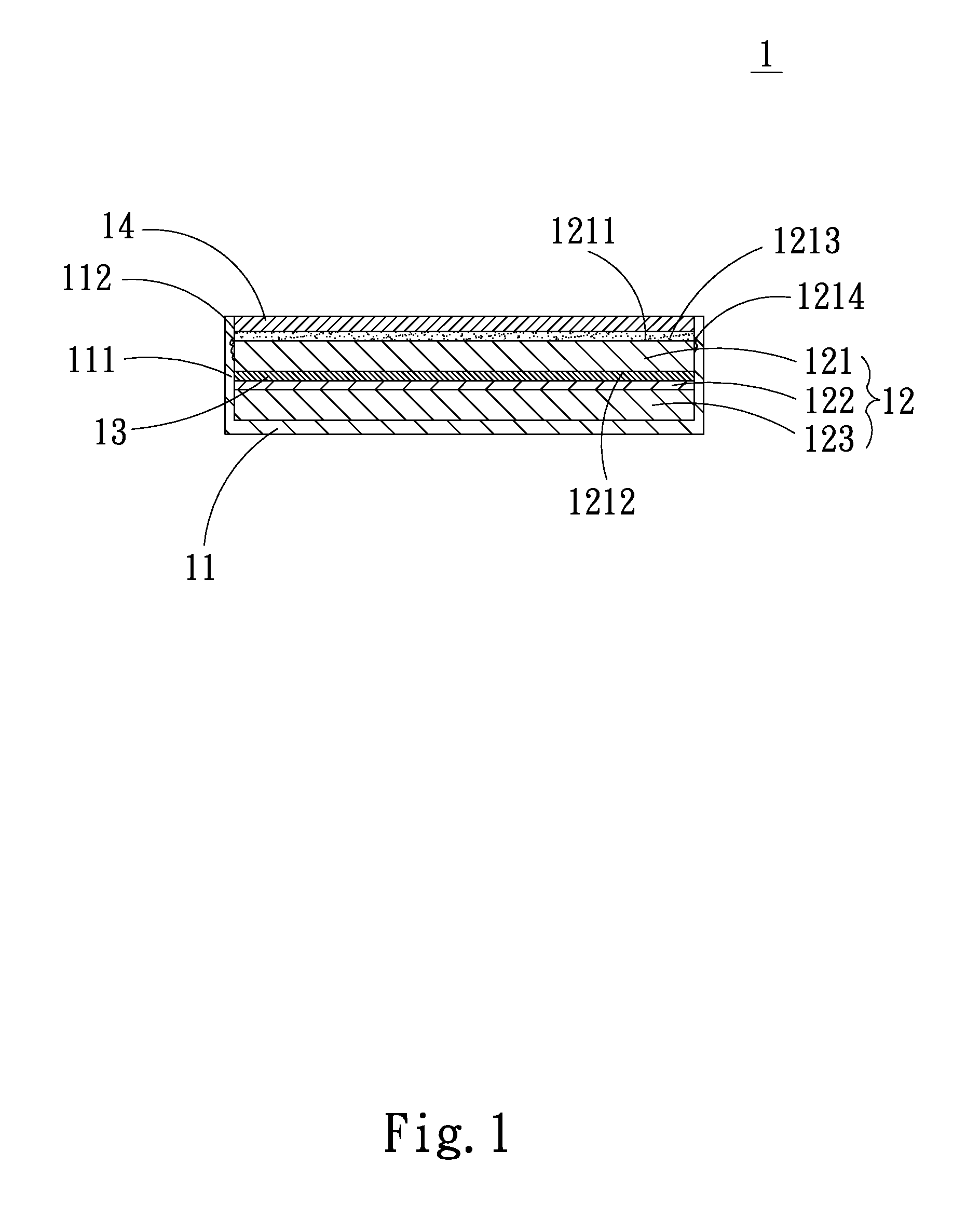
[0021]Please refer to FIG. 1 that is a sectional view of a touch panel 1 according to a first preferred embodiment of the present invention. As shown, the touch panel 1 in the first preferred embodiment includes a backlight module 11, a liquid crystal display unit (LCD display unit) 12, a capacitive sensing layer 13, and a transparent substrate 14.

[0022]The backlight module 11 has at least one raised wall portion 111 formed along an outer periphery thereof to enclose a receiving space 112.

[0023]The LCD display unit 12 is arranged in the receiving space 112. The LCD display unit 12 includes a first glass substrate 121, a liquid crystal layer 122 and a second glass substrate 123 sequentially stacked from top to b...


PUM

PropertyMeasurementUnit
adhesiveaaaaaaaaaa
transparentaaaaaaaaaa
timeaaaaaaaaaa

Abstract

A touch panel and a method of manufacturing same are disclosed. The touch panel includes a backlight module, an LCD display unit disposed in a receiving space enclosed in a raised wall portion of the backlight module, a capacitive sensing layer arranged on one side of a first glass substrate of the LCD display unit, and a transparent substrate bonded by an adhesive layer to one side of the LCD display unit opposite to the backlight module. Any extra amount of the adhesive layer flowing out from between the LCD display unit and the transparent substrate forms an overflowed adhesive portion, which is also located in the receiving space and shielded by the raised wall portion of the backlight module. Therefore, the step of removing the overflowed adhesive portion can be saved to reduce the labor and time cost for assembling the touch panel.

Description

[0001]This application claims the priority benefit of Taiwan patent application number 101130070 filed on Aug. 20, 2012.FIELD OF THE INVENTION[0002]The present invention relates to a touch panel and a method of manufacturing same; and more particularly to a touch panel and a method of manufacturing same that can reduce the labor and time cost for assembling the touch panel.BACKGROUND OF THE INVENTION[0003]Due to the quick development in the information technological and communication network fields, various kinds of electronic information products have become highly popular among consumers. Meanwhile, touch panels for electronic information products are also quickly developed. According to the sensing principles thereof, the currently available touch panels can be classified into four major types, namely, resistive, capacitive, electromagnetic, and optical touch panels. Among other, the capacitive touch panel is characterized by its good dust resistance, fire resistance and high def...

Claims


Application Information

Patent Timeline
Patent Type & Authority Applications(United States)
IPC IPC(8): G06F3/044B32B37/12
CPCB32B37/12B32B2307/412B32B2457/202B32B2457/208G02F1/13338G06F3/0443Y10T156/10
Inventor LIN, CHIH-CHUNG
Owner LIN CHIH CHUNG
Why Eureka
Try Eureka