Electro-mechanical transducer element, liquid droplet ejecting head, image forming apparatus, and electro-mechanical transducer element manufacturing method
- Summary
- Abstract
- Description
- Claims
- Application Information
AI Technical Summary
Benefits of technology
Problems solved by technology
Method used
Image
Examples
first embodiment
[0090]From now on, the present invention is described in more detail by describing an embodiment.
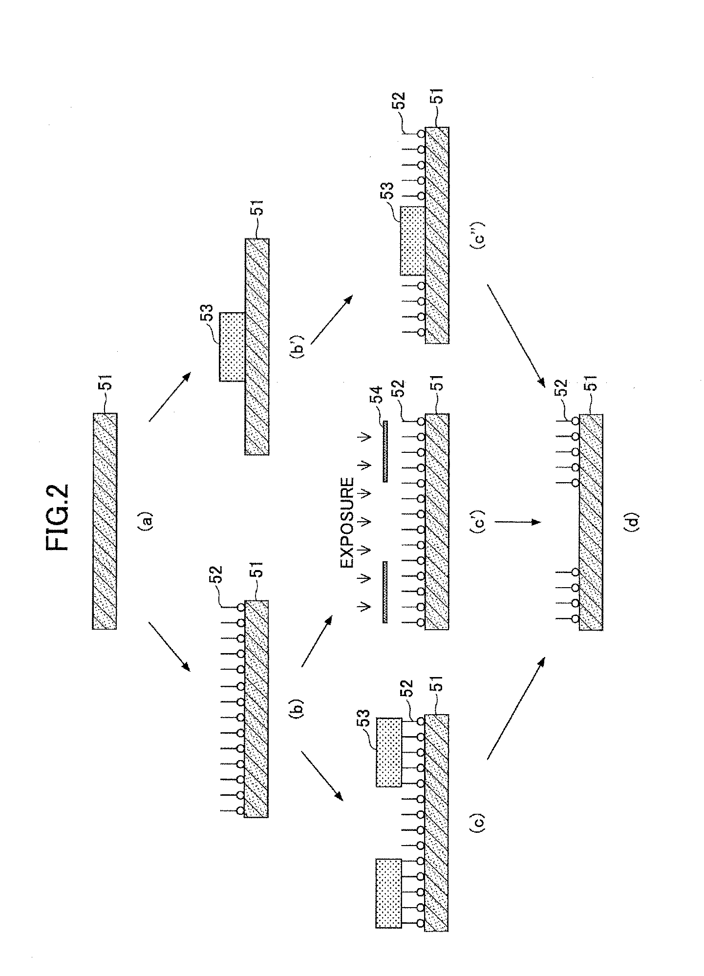
[0091]A quality of surface of a substrate, which a Pt electrode is formed on the surface of the substrate by sputtering, is modified by the above-described step of modifying a quality of surface. As an SAM film, alkanethiol (CH3(CH2)-SH) is used.
[0092]An angle of contact with respect to pure water of the SAM film formed in the first embodiment is 92 degrees, while an angle of contact of Pt on the substrate whose SAM film is removed is 54 degrees. This means that a quality of surface of a portion in which the SAM film is formed is modified to hydrophobic (in other words, a Pt portion is hydrophilic) by the SAM film.
[0093]A PZT precursor solution is applied to a patterned hydrophilic region by a below-described inkjet applying apparatus.
[0094]FIG. 4 is a schematic perspective diagram for explaining one example of the inkjet applying apparatus which can be used in the first embodiment.
[0095...
second embodiment
[0115]Using a method similar to that in the first embodiment, a step of modifying a quality of surface of a first electrode formed on a ground to a predetermined pattern; a step of applying a Sol-gel solution including a precursor of the electro-mechanical transducer film by an inkjet scheme to a region, a quality of surface of which a region is not modified, on the first electrode; and a step of thermally processing the applied Sol-gel solution are repeated to obtain a PZT film according to a second embodiment.
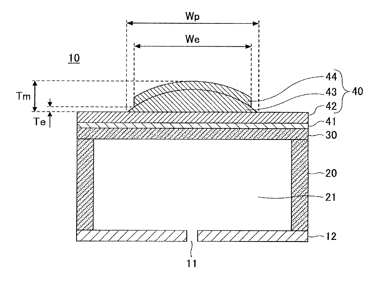
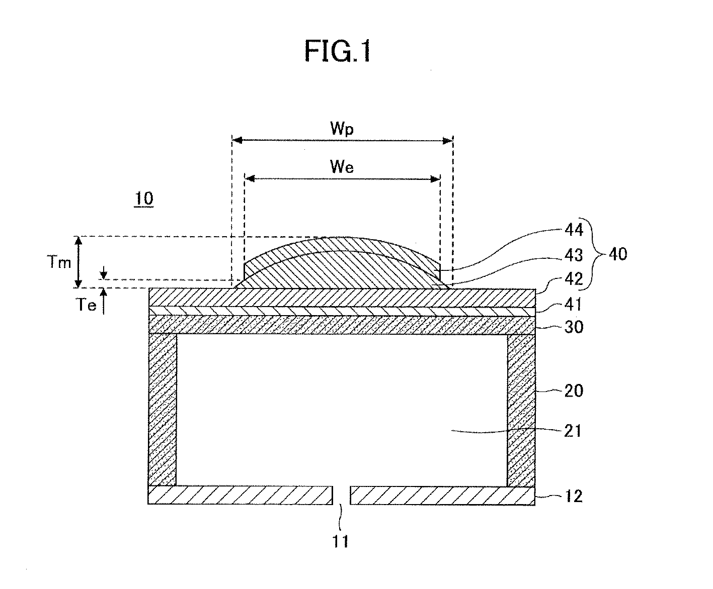
[0116]A width in a short-length direction (in a cross section in a direction perpendicular to a longitudinal direction) is approximately 52 μm, while a thickness (in other words, a maximum film thickness) at a center portion in the short-length direction is approximately 2 μm.
[0117]FIG. 8 is a schematic diagram for explaining an example of a film thickness distribution shape of the electro-mechanical transducer film according to the second embodiment. More specifically, a sol...
third embodiment
[0128]Using a method similar to that in the first embodiment, a step of modifying quality of surface of a first electrode formed on a substrate to a predetermined pattern; a step of applying a Sol-gel solution including a precursor of the electro-mechanical transducer film by an inkjet scheme to a region on the first electrode, a quality of surface of which a region is not modified; and a step of thermally processing the applied Sol-gel solution are repeated to obtain a PZT film according to a third embodiment.
[0129]A film thickness at a center portion in a short-length direction (in other words, a maximum film thickness) of the PZT film according to the third embodiment is approximately 2000 nm. It is designed such that, for the PZT film according to the third embodiment, a length in the short-length direction becomes approximately 50 μm, while a length in the longitudinal direction becomes approximately 1000 μm.
[0130]On the obtained PZT film is formed Platinum as a second electrod...
PUM
 Abstract
Description
Claims
Application Information
 - R&D
- Intellectual Property
- Life Sciences
- Materials
- Tech Scout
- Unparalleled Data Quality
- Higher Quality Content
- 60% Fewer Hallucinations
Browse by: Latest US Patents, China's latest patents, Technical Efficacy Thesaurus, Application Domain, Technology Topic, Popular Technical Reports.
© 2025 PatSnap. All rights reserved.Legal|Privacy policy|Modern Slavery Act Transparency Statement|Sitemap|About US| Contact US: help@patsnap.com


