DC-Link Voltage Balancing Control for Multilevel Inverters

a multi-level inverter and voltage balancing technology, applied in the field of electric power conversion systems, can solve the problems of reducing the performance of multi-level inverters, collapse of some of these voltages under a wide range of operating conditions, and adding to the cost and complexity of the system

Active Publication Date: 2014-02-20
MITSUBISHI ELECTRIC RES LAB INC
View PDF2 Cites 27 Cited by
  • Summary
  • Abstract
  • Description
  • Claims
  • Application Information

AI Technical Summary

Benefits of technology

[0007]It is an object of some embodiments of an invention to provide a method for a DC-link voltage balancing control of an inverter, e.g., a multilevel inverter. It is further object of some embodiments to control the fluctuation of the voltages of the DC-link capacitors of the inverter in real time. It is further object of some embodiments of the invention to control the voltages of the DC-link capacitors such that a difference between desired and expected voltages of the capacitors is minimized. It is further object of some embodiments of the invention to provide various approaches to control the voltages in a computationally efficient manner.

Problems solved by technology

However, the inherent voltage drift of the DC-link capacitors of the multilevel inverters will degrade the performance of the multilevel inverters, in terms of higher voltage pressure on the power devices, higher harmonics, higher electromagnetic interference, and so on.
If the voltage drift of the DC-link capacitors is not limited during the operation of the multilevel inverter, then the unbalances of DC-link capacitor voltages even lead to the collapse of some of these voltages under a wide range of operating conditions.
However, A. Jouanne's method requires additional power hardware, which adds to the cost and complexity of the system.
However, A. Yazdani's method is proper for a double converter back-to-back application, but not suitable for a stand-alone multilevel inverter.
In S. Busquets's method, however, the addition of the three phase currents is required to be zero, which limits the application of the method, and the complexity of the method will be increased dramatically with the increase of the inverter level.
Moreover, the duty cycles of the space vectors are fixed in M. Saeedifard's and L. Su's methods, which can't provide the best control effect for all operation conditions.
In addition, in M. Saeedifard's method, the objective function needs to be differentiable, which makes M. Saeedifard's method ineffective when nondifferentiable objective functions are adopted.

Method used


Image

  • DC-Link Voltage Balancing Control for Multilevel Inverters
  • DC-Link Voltage Balancing Control for Multilevel Inverters
  • DC-Link Voltage Balancing Control for Multilevel Inverters

Examples


Embodiment Construction

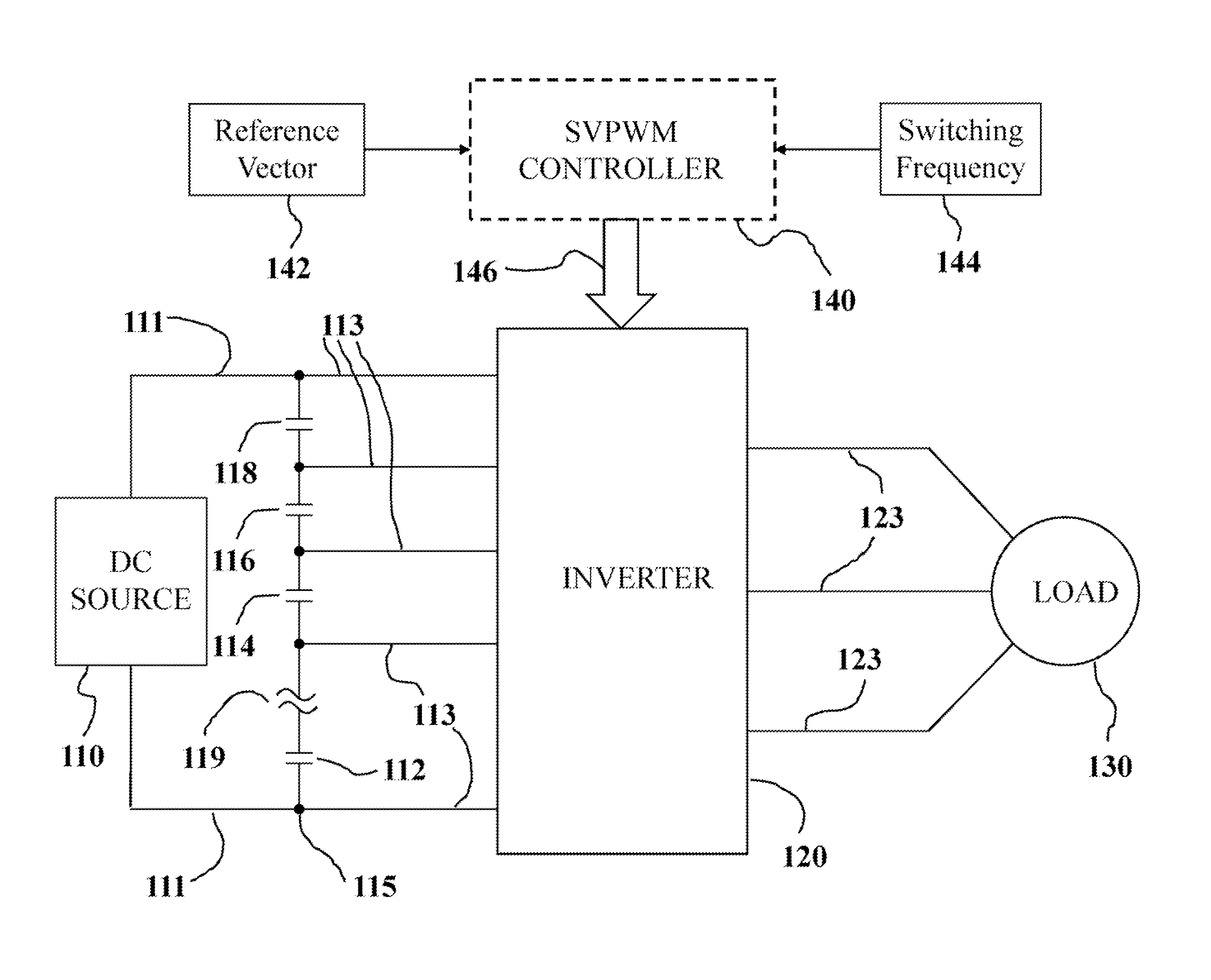
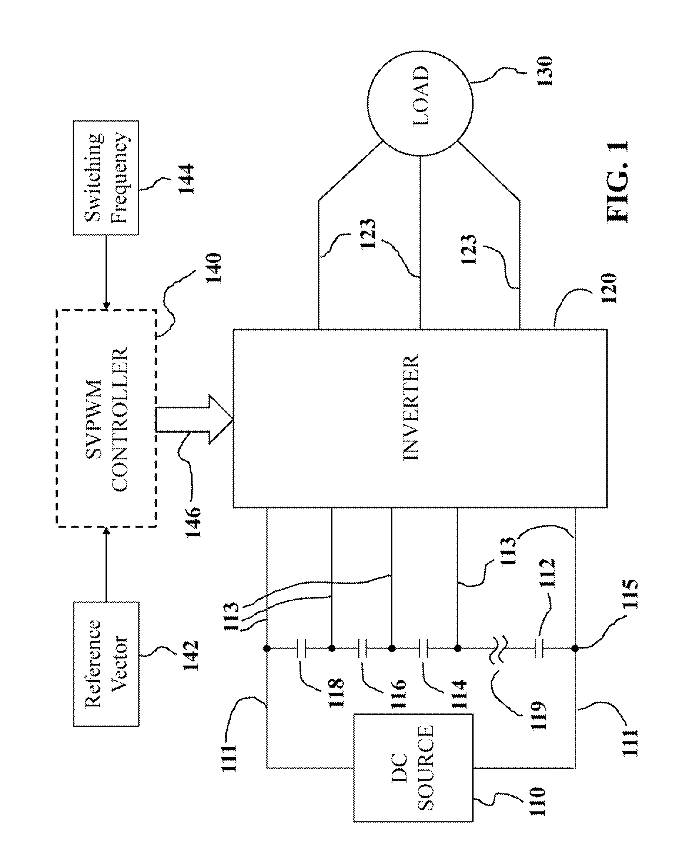
[0045]Multilevel inverters are used in high-power medium-voltage applications due to their superior performance compared to two-level inverters. Space vector pulse width modulation (SVPWM) is preferred among various modulation strategies for multilevel inverters because SVPWM offers significant flexibility to optimize switching waveforms, and because SVPWM is well suitable for digital signal processor implementation. In order to reduce the harmonics and voltage surges during the switching transients, the “Nearest Three Vectors” (NTV), is commonly adopted for SVPWM.

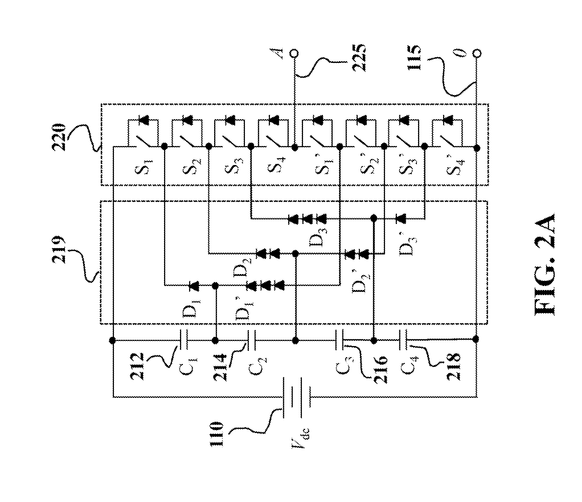
[0046]For an n-level inverter, however, there are n3 switching states and 6(n−1)2 triangles in the space vector diagram. The complexity of conventional SVPWM for multilevel inverters is due to the difficulty in determining the location of the reference vector, the calculation of duty cycles, and the determination and selection of switching states. As the level of the inverter increases, the increased number of switching st...


PUM


Abstract

A method for balancing a voltage of an inverter determines an expected voltage of a capacitor based on a voltage of the capacitor at a start of a switching cycle and determines a duty cycle minimizing a value of an objective function representing a difference between the expected voltage of the capacitor and a desired voltage of the capacitor. A switching sequence controlling the inverter is selected based on the duty cycle.

Description

RELATED APPLICATIONS[0001]This application is copending with of U.S. patent application Ser. No. 13 / 547,562 entitled “Space Vector Modulation for Multilevel Inverters” filed by Deng et al. on Jul. 12, 2012, and incorporated herein by reference.FIELD OF THE INVENTION[0002]This invention relates generally to electrical power conversion systems, and more particularly to DC-link voltage balancing control for a multilevel inverter.BACKGROUND OF THE INVENTION[0003]Multilevel inverters are widely used in high-power high-voltage applications due to advantageous performance over two-level inverters, including reduced voltage pressure or tension on the power devices, lower harmonics, lower instantaneous rate of voltage change (dv / dt), and lower common-mode voltage. However, the inherent voltage drift of the DC-link capacitors of the multilevel inverters will degrade the performance of the multilevel inverters, in terms of higher voltage pressure on the power devices, higher harmonics, higher ...

Claims


Application Information

Patent Timeline
Patent Type & Authority Applications(United States)
IPC IPC(8): H02M7/44
CPCH02M7/487H02M7/4835
Inventor TEO, KOON HOODENG, YI
Owner MITSUBISHI ELECTRIC RES LAB INC
Why Eureka
Try Eureka