Rotary connector

a technology of rotary connectors and connectors, applied in current collectors, electric/fluid circuits, vehicle components, etc., can solve the problems of difficult molding of movable bodies, insufficient reduction of friction coefficient, and production problems such as difficulty in molding, so as to reduce cost, reduce noise generation, and simplify the effect of structur

Inactive Publication Date: 2014-02-20
ALPS ALPINE CO LTD
View PDF3 Cites 9 Cited by
  • Summary
  • Abstract
  • Description
  • Claims
  • Application Information

AI Technical Summary

Benefits of technology

[0010]The present disclosure is made in view of the related art, and provides a rotary connector whose structure can be simpli...

Problems solved by technology

If the dimension d is greater than 2.0 mm, the groove portions 4c are too deep, and a production problem of the difficulty of molding arises.
If the angle θ is smaller than 5 degrees, the groove port...

Method used


Image

  • Rotary connector
  • Rotary connector
  • Rotary connector

Examples


Embodiment Construction

[0025]The following description is intended to convey a thorough understanding of the embodiments described by providing a number of specific embodiments and details involving a rotary connector. It should be appreciated, however, that the present invention is not limited to these specific embodiments and details, which are exemplary only. It is further understood that one possessing ordinary skill in the art, in light of known systems and methods, would appreciate the use of the invention for its intended purposes and benefits in any number of alternative embodiments, depending on specific design and other needs.

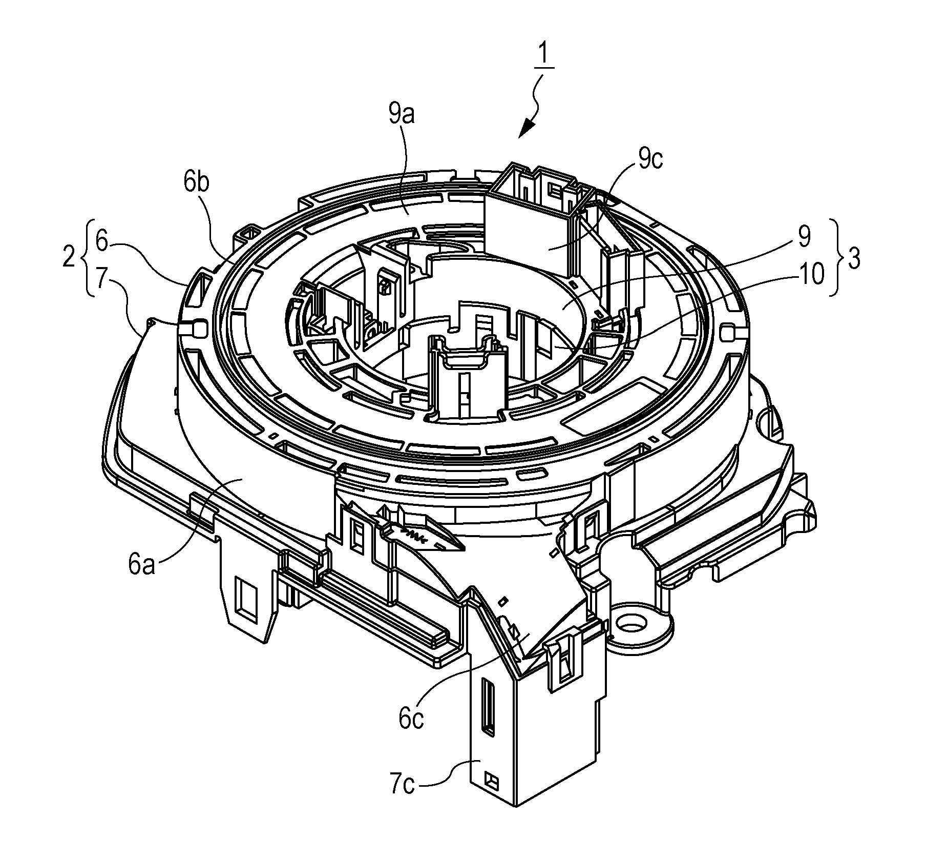
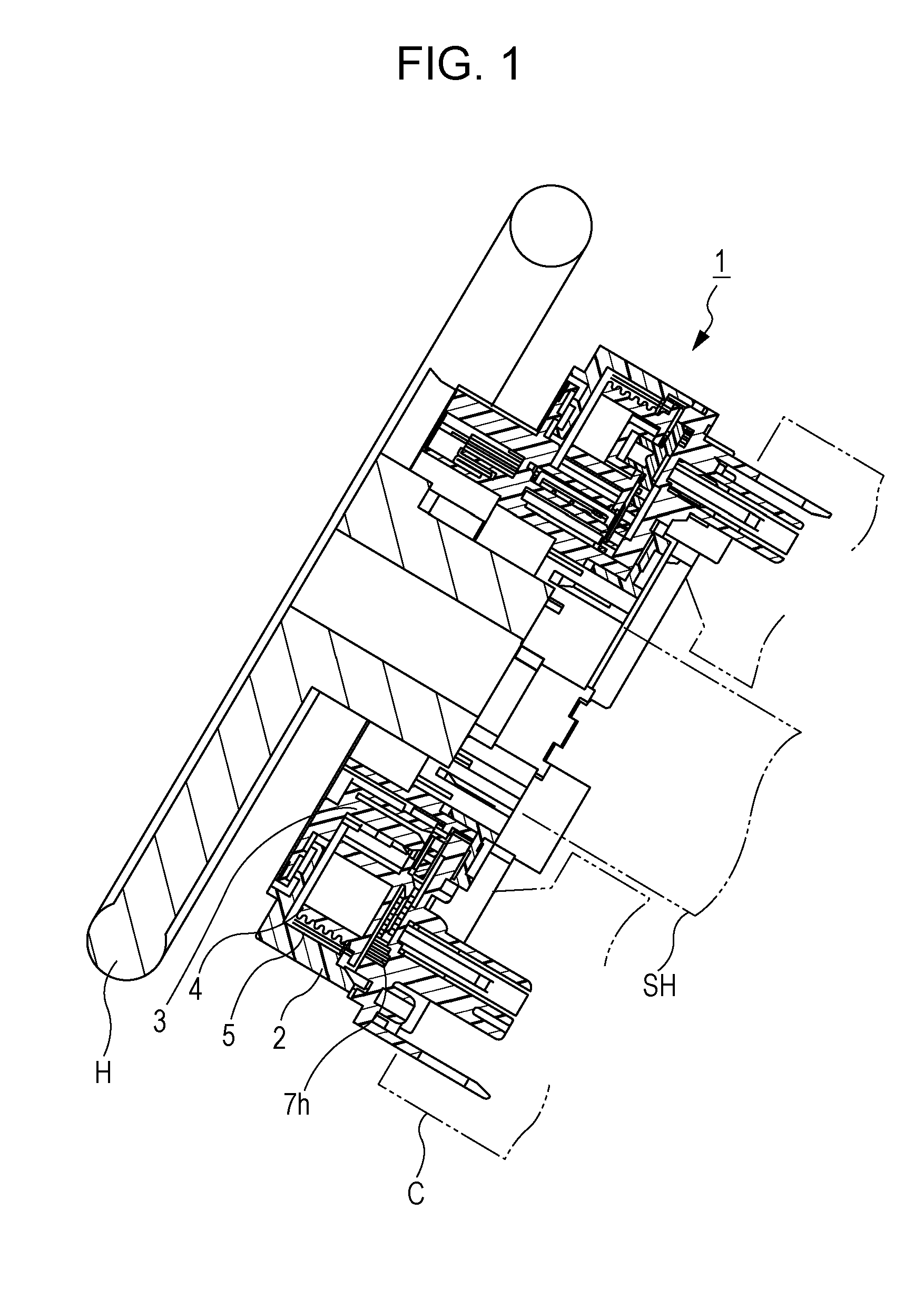
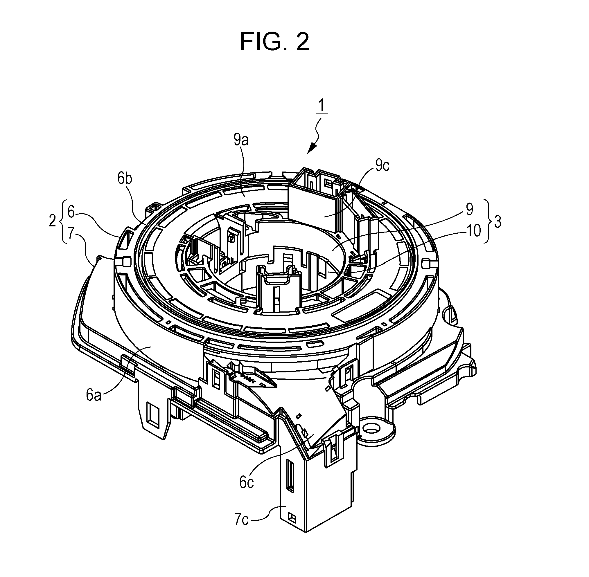
[0026]Various exemplary embodiments of the present disclosure will be described with reference to the drawings below. As shown in FIG. 1, a rotary connector 1 according to the exemplary embodiments may include a stationary-side housing 2, a movable-side housing 3, a movable body 4, and flat cables 5, and may be incorporated and used in an automotive steering system. The ste...


PUM


Abstract

In a rotary connector in which a movable body rotating with rotation and revolution of a planetary gear and a flat cable having a reversed portion are housed within a housing space defined between outer and inner cylindrical bodies, restricting walls extending in the circumferential direction with an opening therebetween are erected on the movable body molded of resin, the reversed portion is passed through the opening, and the radial movement of the flat cable is restricted. A plurality of groove portions are formed in the inner peripheral surfaces of the restricting walls so as to be continuous with one another along the circumferential direction, and the depth d of the groove portions and the central angle θ corresponding to the length in the circumferential direction of the groove portions are set within ranges of 0.5 mm≦d≦2.0 mm and 5 degrees≦θ≦30 degrees.

Description

CLAIM OF PRIORITY[0001]This application contains subject matter related to and claims the benefit of Japanese Patent Application No. 2012-181618 filed on Aug. 20, 2012, the entire contents of which is incorporated herein by reference.BACKGROUND OF THE DISCLOSURE[0002]1. Field of the Disclosure[0003]The present disclosure relates to a rotary connector that is incorporated in an automotive steering system and is used as electrical connecting means for an airbag system or the like, and more specifically, to a rotary connector in which a flat cable is wound within a housing space between a stationary-side housing and a movable-side housing in a state where the winding direction of the flat cable is reversed via a reversed portion.[0004]2. Description of the Related Art[0005]A rotary connector includes a stationary-side housing having an outer cylindrical body and a movable-side housing having an inner cylindrical body, the stationary-side housing and the movable-side housing being dispo...

Claims


Application Information

Patent Timeline
IPC IPC(8): B60R16/027
CPCB60R16/027
Inventor AIKAWA, KEISUKEASAKURA, TOSHIAKITAKAHASHI, SEISHI
Owner ALPS ALPINE CO LTD
Why Eureka
Try Eureka