Object transfer method and object processing apparatus

a technology of object transfer and processing apparatus, which is applied in the direction of electrical programme control, program control, instruments, etc., can solve the problems of reducing the productivity changing the rate limiting factor for the time required for the processing of multi-chamber type processing apparatus, and limiting the productivity. , to achieve the effect of reducing the processing time and limited productivity

Inactive Publication Date: 2014-02-20
TOKYO ELECTRON LTD
View PDF10 Cites 0 Cited by
  • Summary
  • Abstract
  • Description
  • Claims
  • Application Information

AI Technical Summary

Benefits of technology

[0009]In view of the above, the present invention provides an object transfer method and an object processing apparatus, which can solve the problem of limited the productivity even if the processing time is shortened.

Problems solved by technology

However, once the reduction in the processing time of the respective processes is achieved, a rate limiting factor for the time required for the processing of the multi-chamber type processing apparatus is changed from a process rate limiting to a transfer rate limiting.
For this reason, even if the processing time is substantially reduced, the improvement in the productivity is limited.

Method used


Image

  • Object transfer method and object processing apparatus
  • Object transfer method and object processing apparatus
  • Object transfer method and object processing apparatus

Examples


first embodiment

[0028](Apparatus for Processing an Object)

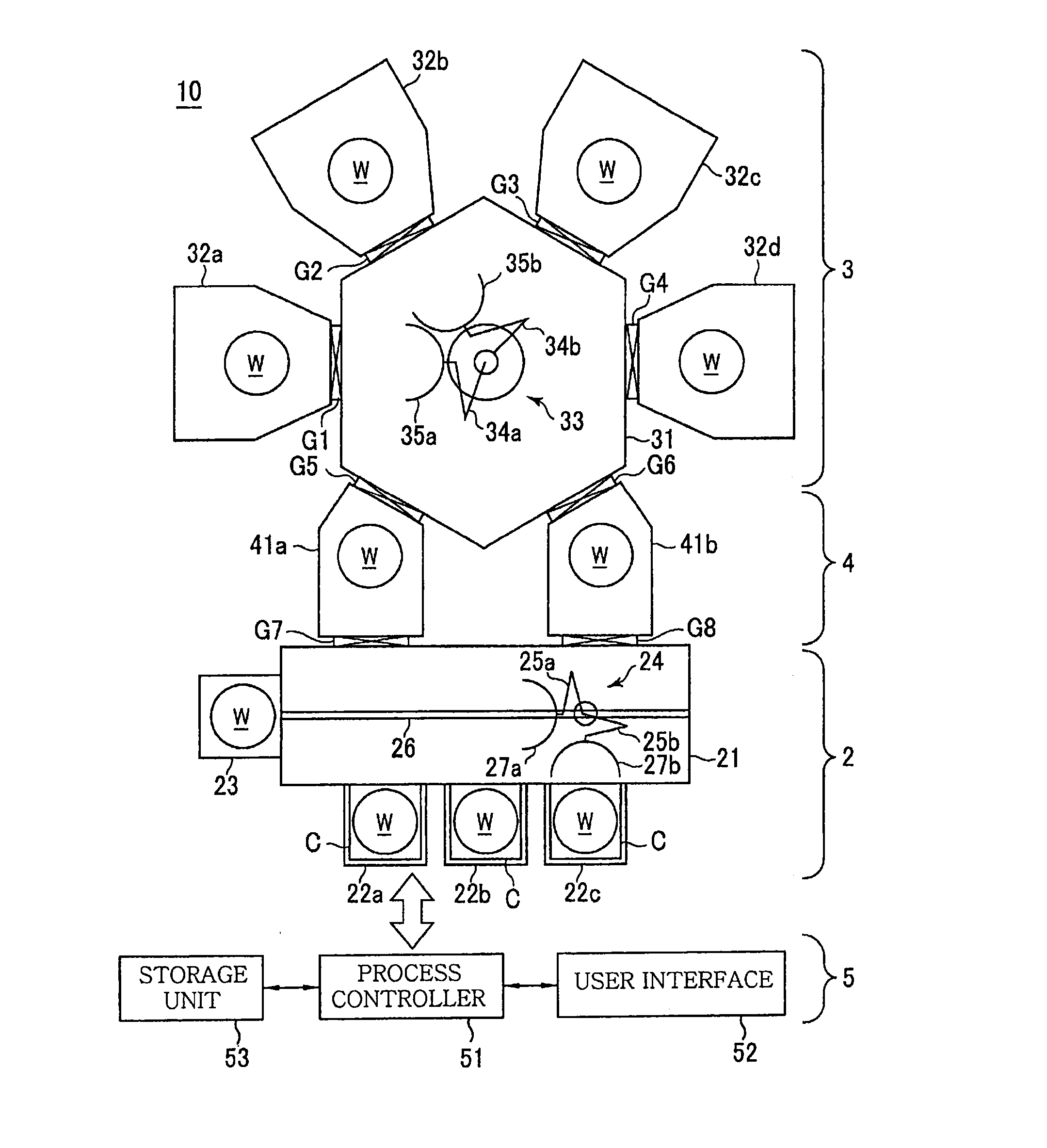
[0029]FIG. 1 is a top view schematically showing an example of an object processing apparatus capable of performing an object transfer method in accordance with a first embodiment of the present invention. In this example, a multi-chamber (cluster tool) type semiconductor manufacturing apparatus using a semiconductor wafer as an object to be processed is described as an example of the object processing apparatus.

[0030]As shown in FIG. 1, a semiconductor manufacturing apparatus 1 includes: a loading / unloading unit 2 for loading and unloading a semiconductor wafer (hereinafter, referred to as “wafer”) W as an object to be processed between the semiconductor manufacturing apparatus 1 and the outside; a processing unit 3 for processing the wafer W; a load-lock unit 4 for loading and unloading the wafer W between the loading / unloading unit 2 and the processing unit 3; and a control unit 5 for controlling the semiconductor manufacturing apparatus ...

second embodiment

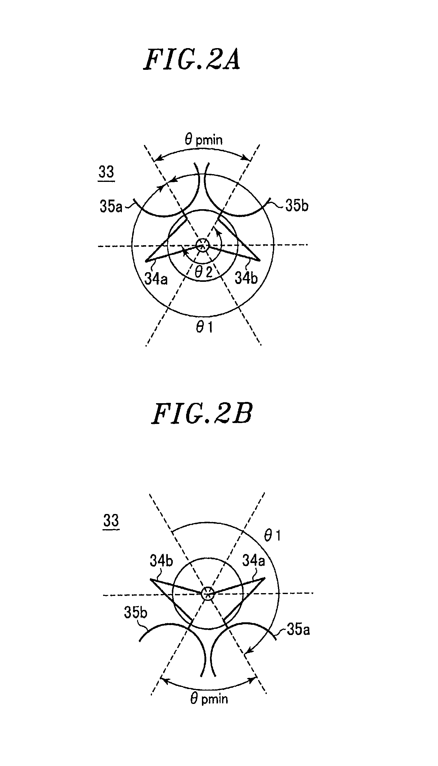
[0098]In the transfer mechanism 33, the transfer arms 34a and 34b are configured to operate individually. By using this transfer mechanism 33, the transfer method for simultaneously exchanging a processed wafer and an unprocessed wafer can be implemented.

[0099]In a second embodiment, the transfer method for simultaneously exchanging a processed wafer and an unprocessed wafer and the transfer method of the first embodiment are switched depending on the process recipe time.

[0100]Prior to the description of the second embodiment, an example of the method for simultaneously transferring a processed wafer and an unprocessed wafer which can be used in the second embodiment will be described.

[0101]FIGS. 7A to 7F are top views showing transfer sequences of an example of an object transfer method that can be used in the second embodiment of the present invention. FIG. 4C depicts a timing diagram of the object transfer method. Further, in FIGS. 7A to 7F, the illustration of the loading ports ...


PUM


Abstract

Disclosed are an object transfer method and an object processing apparatus. The object transfer method includes: extending a first transfer arm into a processing chamber, and retracting the same after a first pick picking up an processed object accommodated in the processing chamber; rotating the first and second transfer arms to move a second pick holding an unprocessed object to a transfer position in front of the processing chamber and to move the first pick holding the processed object to a position adjacent to a transfer position in front of a load-lock chamber; extending the second transfer arm into the processing chamber, and retracting the same after accommodating the unprocessed object held by the second pick in the processing chamber; and rotating the second transfer arm to move the second pick holding no object to the transfer position in front of the load-lock chamber.

Description

FIELD OF THE INVENTION[0001]The present invention relates to a method for transferring an object to be processed and an apparatus for processing an object.BACKGROUND OF THE INVENTION[0002]In manufacturing an electronic device, an object to be processed is used, and various processes such as film formation, etching, and the like are performed on the object. For example, in manufacturing a semiconductor integrated circuit device, a semiconductor wafer is used as an object to be processed, and various processes such as film formation, etching, and the like are performed on the semiconductor wafer. In general, such processes are carried out in separate processing apparatuses. For example, a film forming process is performed in a film forming apparatus having a film forming chamber, and an etching process is performed in an etching apparatus having an etching chamber.[0003]Recently, in order to obtain a processing consistency and suppress an increase in a footprint accompanied by an incr...

Claims


Application Information

Patent Timeline
Patent Type & Authority Applications(United States)
IPC IPC(8): G05B19/418
CPCG05B19/4189H01L21/67742H01L21/67745H01L21/205B25J11/0095H01L21/3065H01L21/67201
Inventor SAKAUE, HIROMITSU
Owner TOKYO ELECTRON LTD
Why Eureka
Try Eureka