

Knitting method and knitting tool
- Summary
- Abstract
- Description
- Claims
- Application Information
AI Technical Summary
Benefits of technology
Problems solved by technology
Method used
Image

Examples
Embodiment Construction
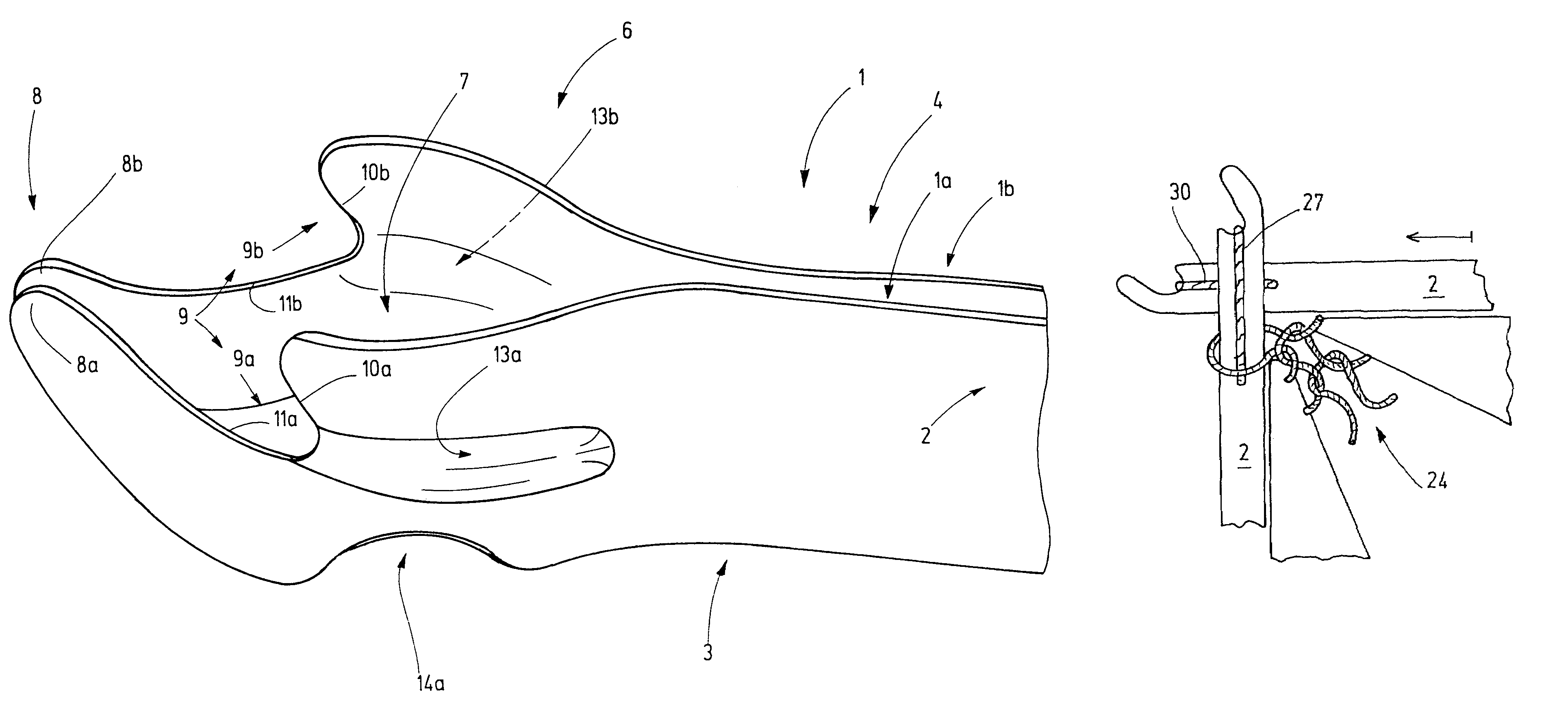
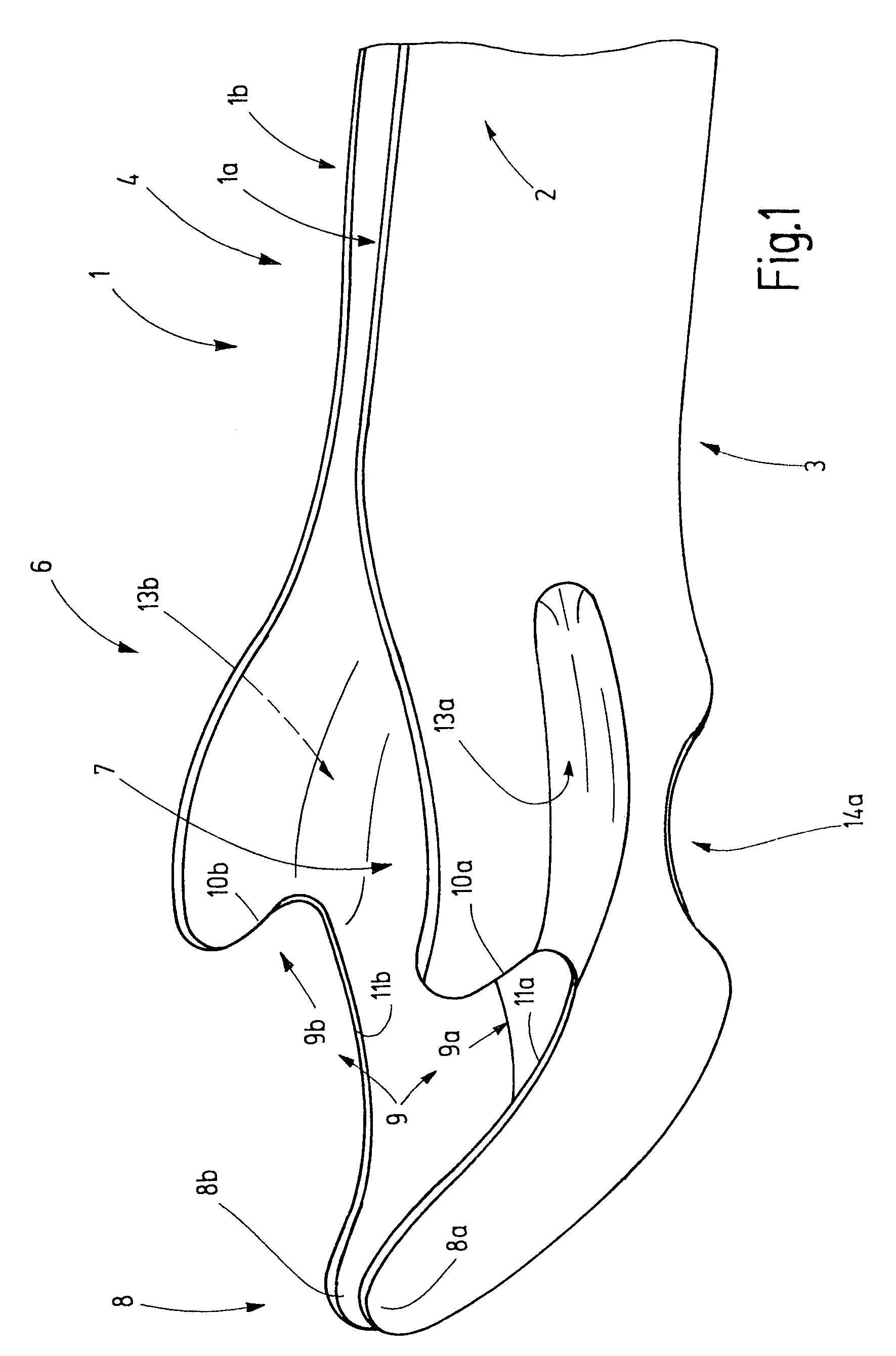
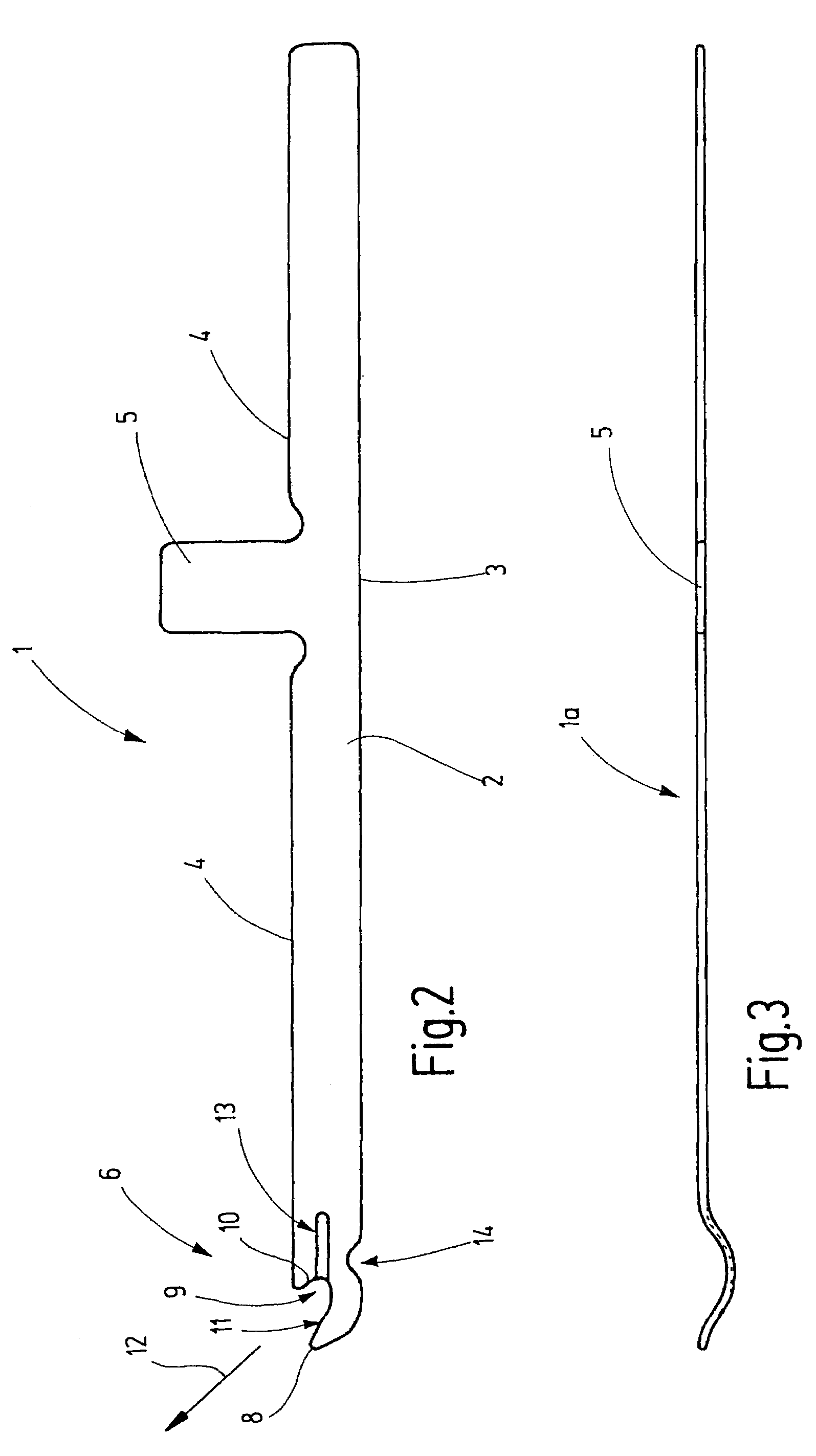
[0031]FIG. 1 shows a knitting tool 1 which, as is shown by FIG. 2, has a longitudinal body 2 made of flat material, for example, said body preferably terminating downward in a straight narrow edge 3. On its opposite side (upper side), the body 2 also has an edge 4, from which projects a foot 5. The foot 5 is used to drive the knitting tool 1, for example, by means of a cam of a knitting machine. However, referring to the present embodiment or to a modified form, said foot may also be used only in order to hold the knitting tool 1 in place on the bar of a loop-forming machine. The foot may be replaced by any other coupling or attachment means.
[0032]On one end 6, the knitting tool 1 has the loop-forming part illustrated separately in FIG. 1, in which case it has also been made clear by FIG. 1 that the knitting tool 1 consists of preferably mirror-symmetrically configured and arranged parts 1a, 1b. These are respectively configured as flat plane parts that are first bent away from each...
PUM
 Abstract
Description
Claims
Application Information