Relay communication system

a communication system and relay technology, applied in the field of relay communication system, can solve the problems of difficult to quickly deal with the problem of operator at the call center notifying

Active Publication Date: 2014-02-20
MURATA MASCH LTD
View PDF6 Cites 2 Cited by
  • Summary
  • Abstract
  • Description
  • Claims
  • Application Information

AI Technical Summary

Benefits of technology

[0011]Therefore, the maintenance terminal can connect to the target terminal quickly in response to the c

Problems solved by technology

However, in the conventional remote maintenance system, it is annoying that the operator at the call center notifies the operator at the maintenance center of the one

Method used


Image

  • Relay communication system
  • Relay communication system
  • Relay communication system

Examples


Embodiment Construction

[0037]In the following, a remote maintenance system will be explained according to various preferred embodiments of the present invention. It should be noted that the following is a non-limiting description of examples of preferred embodiments of the present invention.

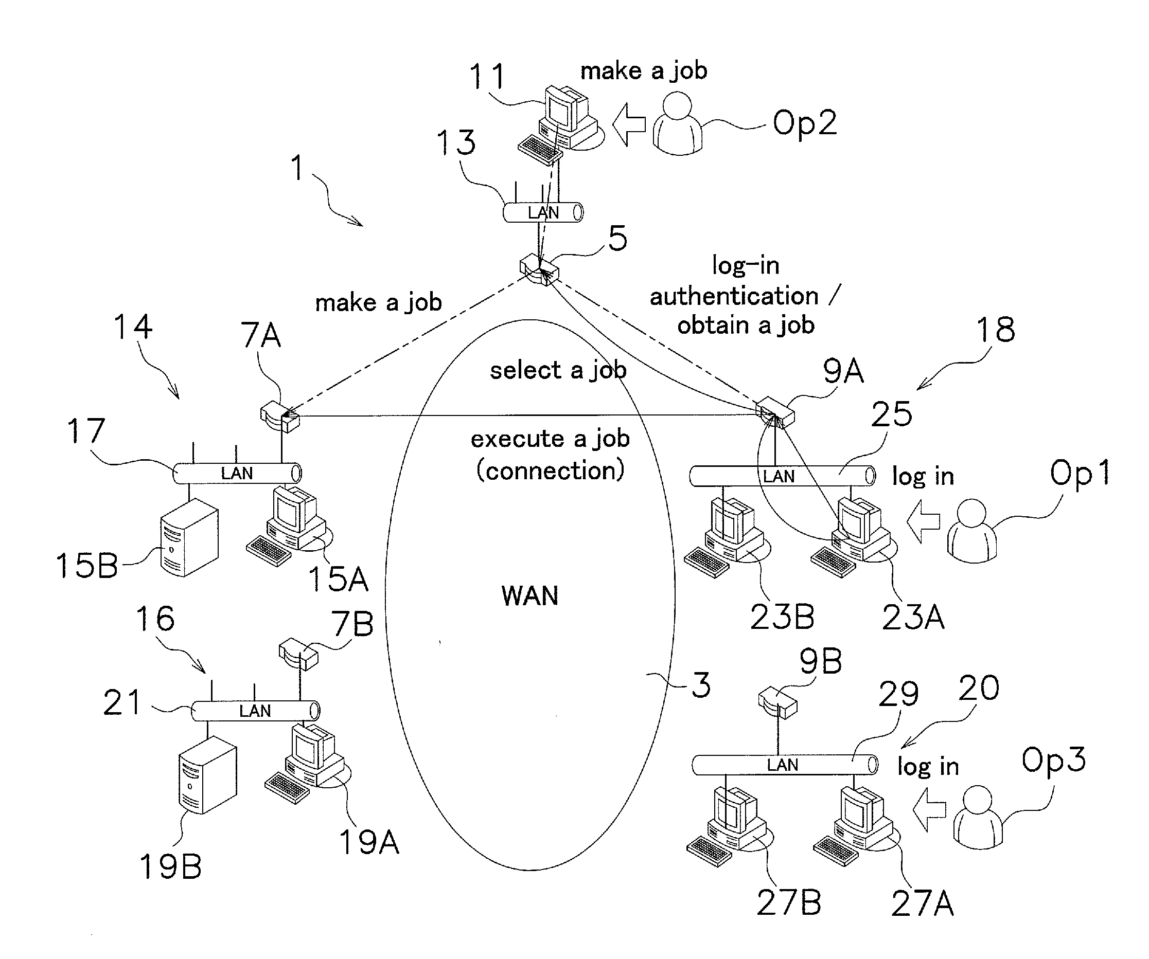
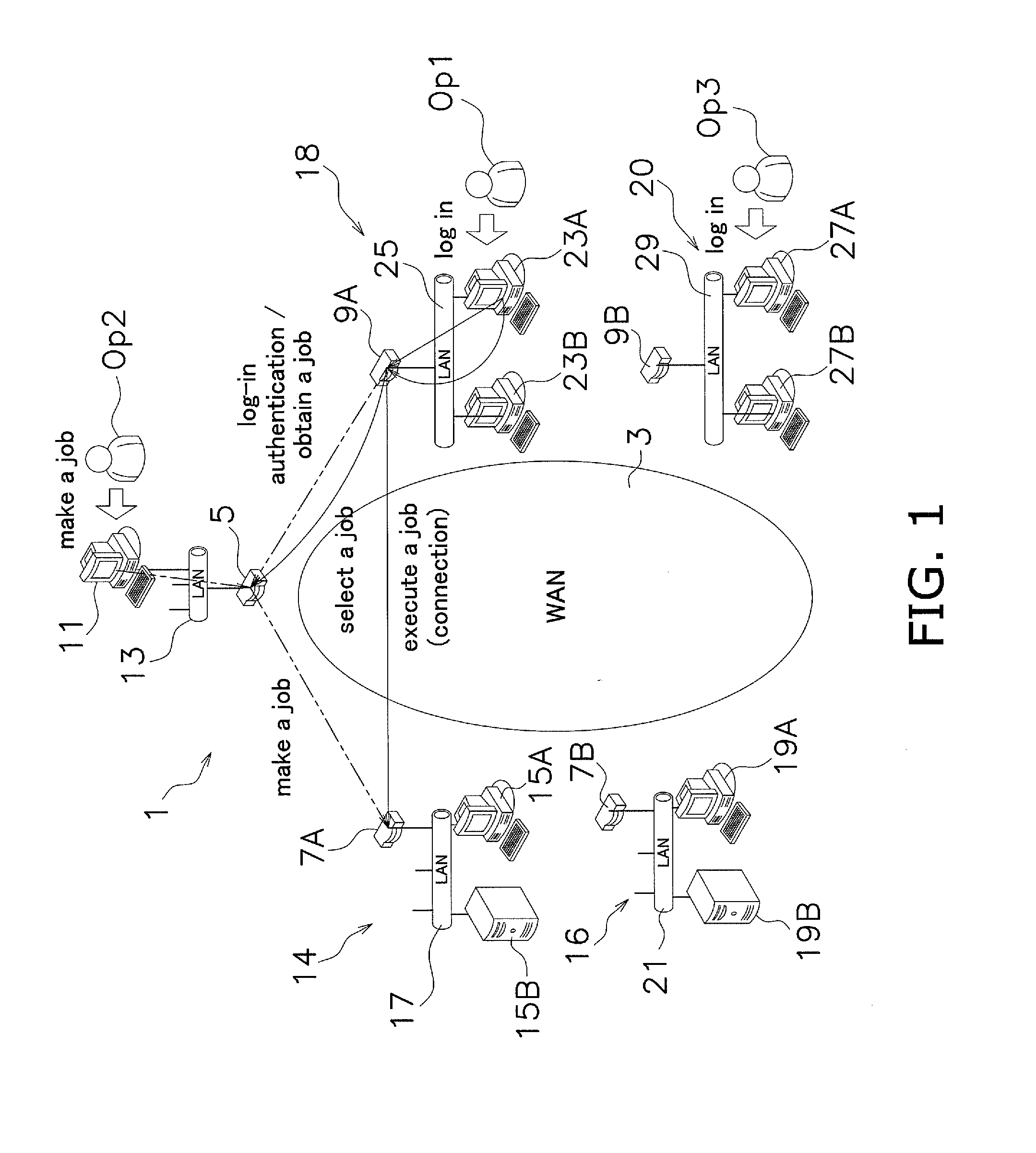
[0038]A brief overview of a relay communication system 1 according to the present preferred embodiment of the present invention will be explained. FIG. 1 is a figure showing a basic structure of the relay communication system. The relay communication system 1 includes client terminals and relay servers connected via a network. Each client terminal is configured to communicate with, via a relay server to which the client terminal is connected, the other relay servers or the client terminal that is connected to the relay server. Each relay server is configured to communicate with other relay servers or with the client terminal connected to the relay server.

[0039]The relay communication system 1 includes a plurality of re...


PUM


Abstract

A center terminal includes a target terminal list storing unit that registers a target terminal and an operator list storing that registers an operator ID and. Each of the maintenance terminal and the target terminal includes a center terminal information storing unit that registers a center terminal. The center terminal makes a connection job that associates a predetermined target terminal with the operator ID and registers the connection job to the center terminal. One of maintenance terminals receives the specific operator ID and the password from a connected client terminal and sends the center terminal an indication whether or not the maintenance terminal can log in to the center terminal, and, if the logging-in is granted, the maintenance terminal is configured to receive the connection job assigned to the operator ID from the center terminal and notify the operator. If the maintenance terminal receives a selection of the connection job from the operator, the maintenance terminal sends an inquiry to the center terminal whether or not the maintenance terminal can execute the connection job. If the connection job is allowed to be executed, the maintenance terminal can be connected to the target terminal included in the connection job.

Description

BACKGROUND OF THE INVENTION[0001]1. Field of the Invention[0002]The present invention relates to a relay communication system where client terminals that are connected with relay servers are connected with each other, as necessary, via the relay servers connected with each other via a network.[0003]2. Description of the Related Art[0004]A remote maintenance system where monitoring and maintenance of electronic equipment that is provided in an office or at home has been in practical use, for example (See, for example, Japanese Laid-Open Patent Application No. 2003-223521). By using the remote maintenance system, a service technician of a maintenance company can perform the maintenance of the electronic equipment without the service technician being on site. In addition, by remotely controlling the electronic equipment, when a problem is caused in the electronic equipment, the service technician of the maintenance company can solve the problem quickly.[0005]As one example of the remot...

Claims


Application Information

Patent Timeline
IPC IPC(8): H04L12/24
CPCH04L41/04H04L41/28H04L63/083H04L12/28H04L67/125H04L67/025H04L41/22H04L41/5061
Inventor TANIMOTO, YOSHIFUMI
Owner MURATA MASCH LTD
Why Eureka
Try Eureka